Al technical title is built by PatSnap Al team. It summarizes the technical point description of the patent document.
A technology of locking mechanism and cone expansion, which is applied in the direction of electromechanical devices, control mechanical energy, electrical components, etc., can solve the problems of not being able to drive objects, and the locking structure cannot be close to objects, etc., to achieve easy transportation and storage, light weight, and design reasonable effect
Active Publication Date: 2016-06-22
GUANGZHOU KEDING AUTOMATION EQUIP CO LTD
View PDF5 Cites 5 Cited by
Summary
Abstract
Description
Claims
Application Information
AI Technical Summary
This helps you quickly interpret patents by identifying the three key elements:
Problems solved by technology
Method used
Benefits of technology
Problems solved by technology
With the acceleration of my country's industrialization process, the motor industry is booming. However, the locking structure of the existing motors on the market cannot be close to the object, so that the object cannot be driven to rotate, which cannot meet the needs of users.
Method used
Image
Click on the blue label to locate the original text in one second.
Reading with bidirectional positioning of images and text.
Examples
Embodiment Construction
[0023] The technical solution of this patent will be further described in detail below in conjunction with specific embodiments.
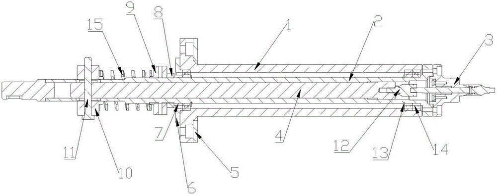
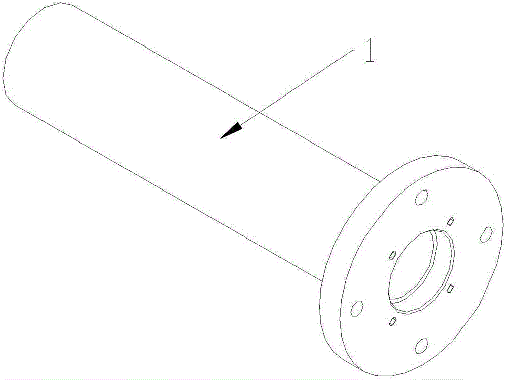
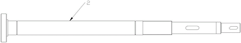
[0024] see Figure 1-11 , a double-cone expansion locking mechanism, including a bearing seat 1, a rotating shaft 2, a double-cone expanding chuck 3, a large pull rod 4, a pull pin shaft 11, a floating joint 12, a bearing 14 and a spring 15, and the rotating shaft 2 The bearing 14 is installed inside the bearing seat 1 and a shaft retaining ring 13 is arranged between the rotating shaft 2 and the bearing seat 1. The large tie rod 4 is installed inside the rotating shaft 2 and fixed by a pull pin shaft 11. The pull pin shaft 11 The outside of the bearing seat 1 is fixed on the rotating shaft 2 by pushing the slider 10 through a spring. A pressure pad 5 is installed on the outside of the bearing seat 1. The lower end of the bearing seat 1 is pressed by the bearing lower gland 6. The bearing lower gland 6 is installed on the On the bearing seat 1, a ...
PUM
Abstract
The invention discloses a biconical expansion locking mechanism, which comprises a bearing seat, a rotation shaft, a biconical expansion chuck, a large pull rod, a pull pin, a floating joint, a bearing and a spring, wherein the rotation shaft is arranged inside the bearing seat; the large pull rod is arranged inside the rotation shaft; the lower end of the bearing seat adopts a bearing down pressing cap for being pressed; the spring is arranged between the bearing down pressing cap and a spring push pull head, and the spring surrounds the outer part of the rotation shaft; and the biconical expansion chuck comprises a positioning core shaft, an expansion sleeve, a bushing and a small pull rod. The device has a simple structure, the design is reasonable, the size is small, the weight is light, and transportation and storage are facilitated; a pure mechanical structure is adopted, the use stability is good, detachability is good, and mounting and replacement are facilitated; through matching between the expansion sleeve, the rotation shaft, the small pull rod and the positioning core shaft, the rotation shaft only needs to be pulled to firmly fasten an article, the article is driven to rotate, the operation is simple and convenient, the use effects are good, the biconical expansion locking mechanism is applicable to motors of various types, the application range is wide, and the service life is long.
Description
technical field [0001] The invention relates to a locking mechanism, in particular to a double-cone expansion locking mechanism. Background technique [0002] The motor, commonly known as the motor, refers to an electromagnetic device that realizes the conversion or transmission of electric energy according to the law of electromagnetic induction. Its main function is to generate driving torque as a power source for electrical appliances or various machines. According to the type of working power supply, motors can be divided into DC motors and AC motors, DC motors can be divided into brushless DC motors and brushed DC motors, and AC motors can be divided into single-phase motors and three-phase motors. According to the structure and working principle, motors can be divided into DC motors, asynchronous motors and synchronous motors. With the acceleration of my country's industrialization process, the motor industry is developing vigorously thereupon, but the locking structu...
Claims
Application Information
Patent Timeline
Application Date:The date an application was filed.
Publication Date:The date a patent or application was officially published.
First Publication Date:The earliest publication date of a patent with the same application number.
Issue Date:Publication date of the patent grant document.
PCT Entry Date:The Entry date of PCT National Phase.
Estimated Expiry Date:The statutory expiry date of a patent right according to the Patent Law, and it is the longest term of protection that the patent right can achieve without the termination of the patent right due to other reasons(Term extension factor has been taken into account ).
Invalid Date:Actual expiry date is based on effective date or publication date of legal transaction data of invalid patent.