Tilting three-rotor wing long-endurance composite aircraft

A tri-rotor, aircraft technology, applied in aircraft, rotorcraft, aircraft parts and other directions, can solve the problems of aircraft reliability and flight safety, affect the aerodynamic efficiency of the wing, technical difficulty and high cost, achieve excellent combat capability, start The effect of low landing conditions and flight safety assurance

Active Publication Date: 2016-06-29
BEIHANG UNIV
View PDF5 Cites 12 Cited by
  • Summary
  • Abstract
  • Description
  • Claims
  • Application Information

AI Technical Summary

Problems solved by technology

However, the tilting mechanism of the V-22 "Osprey" is too complex, and the technical difficulty and cost are higher than those of traditional helicopters. Moreover, the complex power and control system makes the aircraft's reliability and flight safety have great hidden dangers.
Two engines are attached to the outer section of the wing, which limits the wing to a medium aspect ratio, which affects the aerodynamic efficiency of the wing. At the same time, the power and tilt of the engine increase the structural load of the wing, so the structural strength must be increased , thus adding additional weight
In addition, the rotor is shielded by the wings, which affects the efficiency of the rotor

Method used


Image

  • Tilting three-rotor wing long-endurance composite aircraft
  • Tilting three-rotor wing long-endurance composite aircraft
  • Tilting three-rotor wing long-endurance composite aircraft

Examples


Embodiment Construction

[0028] The present invention will be described in further detail below in conjunction with the accompanying drawings.

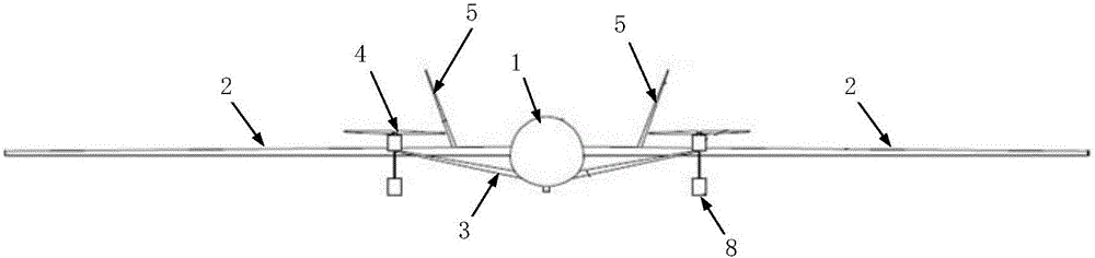
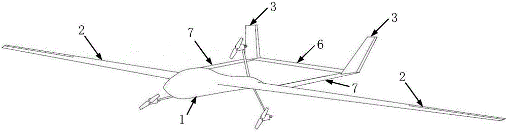
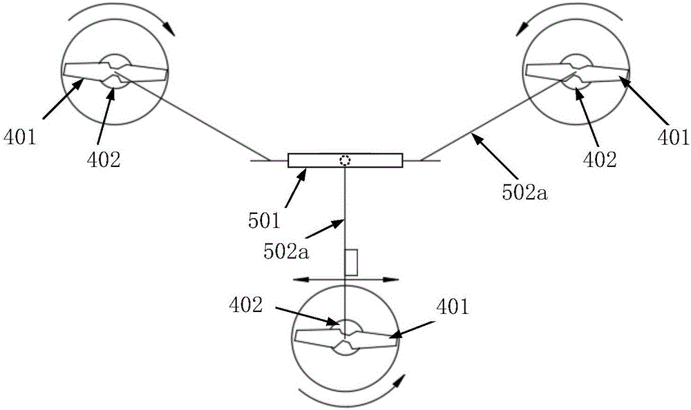
[0029] The tilting three-rotor long-endurance composite aircraft of the present invention includes a fuselage 1, a wing 2, an empennage 3, a three-rotor power system 4 and a tiltable support stand 5, such as figure 1 shown.

[0030] Airborne equipment is loaded on the fuselage 1, such as flight control system, radar, camera, etc., and weapon systems such as machine guns and missiles are mounted to realize flight missions. Both sides of the fuselage 1 are equipped with mutually symmetrical large-aspect-ratio wings 2, and the rear edge of the wing 2 is designed with ailerons. There are two empennages 3, both of which have a stabilizer surface and a rudder surface; the two empennages 3 are respectively installed at the ends of two tail braces 7, adopting a V-shaped empennage layout. The front ends of two tail braces 7 are respectively fixed with the wings 2 on...


PUM


Abstract

The invention discloses a tilting three-rotor wing long-endurance composite aircraft which comprises a three-rotor wing system, an aircraft body, wings with the high aspect ratio and connecting and tilting table supports.The three-rotor wing system is composed of three engines, two of the engines are located in front of the wings, wherein the rotating speed of the engines is same, and the rotating directions of the engines are opposite; another engine is located behind the wings, wherein the reverse torsional moment is eliminated in a vector power mode.The aircraft can vertically take off and land by taking the three-rotor wing system as power; after the aircraft takes off, three rotor wings are integrally tilted and locked through the connecting and tilting table supports, and the aircraft is in a level flight mode.The three-rotor wing power system and the wings with the high aspect ratio can be designed in a decoupling mode through the tiltable table supports, therefore, the aircraft has the capacities of vertically taking off and landing and high-speed long-endurance level flight, and the advantages of being stable, reliable , safe and the like are achieved.The aircraft can be deployed on a small ship with a vertical taking-off and landing platform and also can be deployed on an island with the small area, and no specially-built airport is needed.

Description

technical field [0001] The invention belongs to the field of aircraft design, and relates to a layout form of a vertical take-off and landing composite aircraft, in particular to a layout form of a long-endurance composite aircraft that realizes vertical or short-distance take-off and landing and high-speed level flight by using the tilting of three rotors. Background technique [0002] Whether it is the daily patrol of marine law enforcement ships or the development trend of "air-sea battle", non-aircraft carrier ships urgently need air power that can cooperate with it. However, the take-off and landing conditions of non-aircraft carrier-based aircraft are extremely special, such as: the available deck area is small, the ship fluctuates greatly, and the sea breeze is greatly affected. In addition, on smaller islands and reefs, the environmental conditions are similar to those of ships, and the same requirements are placed on aircraft. Therefore, there is a need for a long-...

Claims


Application Information

Patent Timeline
Patent Type & Authority Applications(China)
IPC IPC(8): B64C27/28B64D47/08
CPCB64C27/28B64D47/08
Inventor 林宏渊李志豪蒋崇文
Owner BEIHANG UNIV
Why Eureka
Try Eureka