Mask plate, evaporation device and evaporation method

A mask plate and evaporation technology, which is applied in vacuum evaporation plating, sputtering plating, ion implantation plating, etc., can solve the problems of color mixing, large gap between the metal mask and the substrate, and achieve the effect of reducing the gap

Inactive Publication Date: 2016-06-29
EVERDISPLAY OPTRONICS (SHANGHAI) CO LTD
5 Cites 28 Cited by

AI-Extracted Technical Summary

Problems solved by technology

[0005] In view of the above problems, embodiments of the present invention provide a mask plate, an evaporation device, and an evaporation method to solve the problem that the gap b...

Method used

[0050] The present invention reduces the gap between the upper surface of the metal mask and the substrate, effectively avoiding the diffusion of the evaporated material to other colors, causing the problem of color mixing. The basic principles, main features and advantages of the present invention have been shown and described above. Those skilled in the art should understand that the ...

Abstract

The invention discloses a mask plate, an evaporation device and an evaporation method. The mask plate comprises mask plate bodies, through holes are formed in the mask plate bodies, and grooves are formed in the positions, where the through holes are not formed, of the first surfaces of the mask plate bodies. During use, the through holes correspond to the color positions required to be coated, the mask plate bodies are close to a substrate, and light resistance separation pillars on the substrate are inserted into the positions of the grooves of the mask plate bodies, so that the gap between the upper end face of a metal mask and the substrate is reduced, and the color mixing problem caused by diffusing evaporation materials to other colors is effectively solved.

Application Domain

Vacuum evaporation coatingSputtering coating +1

Technology Topic

Color mixingEngineering +2

Image

  • Mask plate, evaporation device and evaporation method
  • Mask plate, evaporation device and evaporation method
  • Mask plate, evaporation device and evaporation method

Examples

  • Experimental program(5)

Example Embodiment

[0029] Example 1
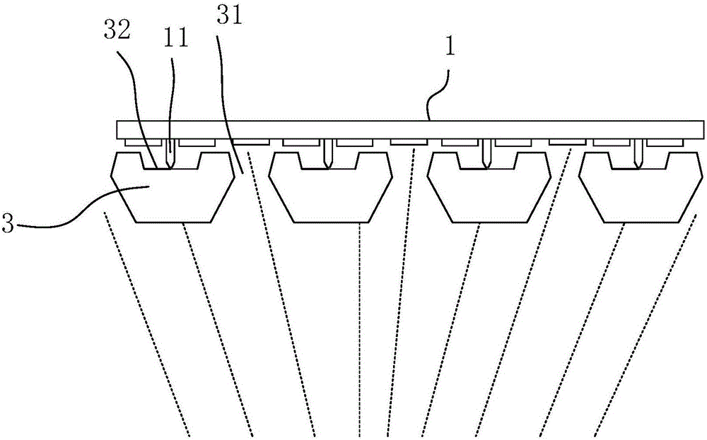
[0030] See figure 2 The mask includes a mask body 3, the mask body is provided with a through hole 31, and the upper end surface of the mask body is provided with a groove 32 for accommodating the photoresist isolation column on the surface of the substrate.
[0031] In this embodiment, the cross section of the groove 32 perpendicular to the direction of the mask body is an inverted trapezoid groove.
[0032] The specific vapor deposition method using the mask includes the following steps:
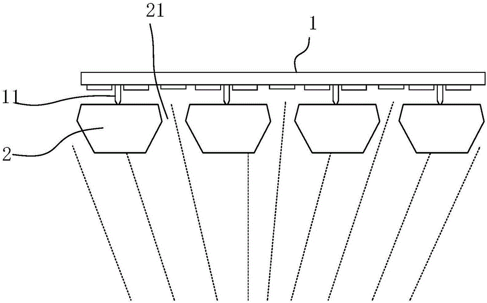
[0033] Provide a substrate 1 to be film-formed, which includes a region to be film-formed and a plurality of photoresist isolation columns 11;
[0034] Providing an evaporation source, the evaporation source and the mask plate are arranged oppositely and fixed in position;
[0035] The substrate 1 to be filmed and the mask body 3 are arranged in parallel and aligned so that the area to be filmed of the substrate 1 corresponds to the through hole 31 of the mask, and the photoresist isolation column 11 of the substrate 1 corresponds to the mask. The inverted trapezoidal groove 32; move the substrate 1 to be filmed along the direction perpendicular to the mask body 3, so that the substrate 1 to be filmed close to the mask to the photoresist isolation column 11 inserted into the bottom of the inverted trapezoidal groove 32; The plating source performs vapor deposition.

Example Embodiment

[0036] Example 2
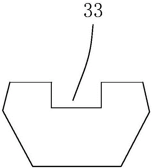
[0037] See image 3 , The mask includes a mask body, the mask body is provided with a through hole, and the upper end surface of the mask body is provided with a groove for containing the photoresist isolation column on the surface of the substrate. In this embodiment, the cross section of the groove 33 perpendicular to the direction of the mask body is square.
[0038] The specific vapor deposition method using the mask includes the following steps:
[0039] The substrate 1 to be filmed and the mask body 3 are arranged in parallel and aligned so that the area to be filmed of the substrate 1 corresponds to the through hole 31 of the mask, and the photoresist isolation column 11 of the substrate 1 corresponds to the mask. The square groove 33; move the substrate 1 to be filmed in the direction perpendicular to the mask body 3, so that the substrate 1 to be filmed is close to the mask to the bottom of the photoresist isolation column 11 inserted into the square groove 33; The plating source performs vapor deposition.

Example Embodiment

[0040] Example 3
[0041] See Figure 4 , The mask includes a mask body, the mask body is provided with a through hole, and the upper end surface of the mask body is provided with a groove for containing the photoresist isolation column on the surface of the substrate. In this embodiment, the cross section of the groove 34 perpendicular to the direction of the mask body is an arc groove.
[0042] The specific vapor deposition method using the mask includes the following steps:
[0043] The substrate 1 to be filmed and the mask body 3 are arranged in parallel and aligned so that the area to be filmed of the substrate 1 corresponds to the through hole 31 of the mask, and the photoresist isolation column 11 of the substrate 1 corresponds to the mask. The arc groove 34; move the substrate 1 to be filmed in the direction perpendicular to the mask body 3, so that the substrate 1 to be filmed is close to the mask to the bottom of the photoresist isolation column 11 inserted into the arc groove 34; The plating source performs vapor deposition.

PUM

no PUM

Description & Claims & Application Information

We can also present the details of the Description, Claims and Application information to help users get a comprehensive understanding of the technical details of the patent, such as background art, summary of invention, brief description of drawings, description of embodiments, and other original content. On the other hand, users can also determine the specific scope of protection of the technology through the list of claims; as well as understand the changes in the life cycle of the technology with the presentation of the patent timeline. Login to view more.

Similar technology patents

Novel anchor bolt steel plate reinforcing fire-proof system and reinforcing method thereof

PendingCN107700868AImprove the bending capacityreduce gap
Owner:重庆市公安消防总队 +1

Transportation system of unmanned restaurant

InactiveCN108542230Areduce gapIncrease the speed of operation
Owner:安徽蒸小皖餐饮股份有限公司

Improved desulphurization device

InactiveCN105797561AReduce input cost and quantityreduce gap
Owner:浙江宝峰热电有限公司

Classification and recommendation of technical efficacy words

  • reduce gap

Single-wheel soil bin test stand

InactiveCN105043788Areduce gapreduce shock
Owner:NANJING AGRICULTURAL UNIVERSITY

Formula for piston of gasoline engine

InactiveCN1362534Areduce gapGood sealing and anti-friction and anti-wear performance
Owner:周芝山
Why Eureka
Try Eureka