Constant-backpressure direct drive type electro hydraulic servo system and control method thereof
An electro-hydraulic servo system and direct-drive technology, applied in the field of servo control, can solve problems such as sudden pressure changes and unbalanced flow of asymmetric hydraulic cylinders, and achieve the effects of simplifying the control scheme, solving the problem of unbalanced flow, and reducing the difficulty of control
- Summary
- Abstract
- Description
- Claims
- Application Information
AI Technical Summary
Problems solved by technology
Method used
Image
Examples
Embodiment 1
[0067] Embodiment 1, the asymmetrical hydraulic cylinder 15 piston rod stretches out the action process:
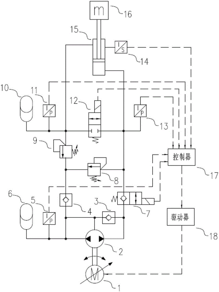
[0068] The controller 17 accepts external commands, and sends a displacement extension command to the driver 18. The driver 18 drives the servo motor 1 to rotate in the forward direction. The servo motor 1 drives the two-way quantitative pump 2 to output oil at the A port and absorb oil at the B port. The conventional accumulator 6 provides two-way Quantitative pump 2B port suction flow, electromagnetic ball valve 7 is electrically connected, the pressure oil at port 2A of the two-way quantitative pump enters the rodless chamber of the asymmetric hydraulic cylinder 15; at the same time, the electromagnetic cut-off valve 12 is not powered, and the rod chamber of the asymmetric hydraulic cylinder 15 is The constant pressure accumulator 10 absorbs the oil discharged from the rod chamber of the asymmetric hydraulic cylinder 15 and maintains a certain pressure; because the forc...
Embodiment 2
[0069] Embodiment 2, the process of retracting the piston rod of the asymmetrical hydraulic cylinder 15:
[0070] The controller 17 accepts external instructions, and sends a displacement retraction instruction to the driver 18. The driver 18 drives the servo motor 1 to rotate in the reverse direction. The servo motor 1 drives the two-way quantitative pump 2 to output oil at the B port and to absorb oil at the A port. The conventional accumulator 6 absorbs the bidirectional Quantitative pump 2B port oil flow, electromagnetic ball valve 7 is electrically connected, bidirectional quantitative pump 2A port absorbs the oil in the rodless chamber of asymmetric hydraulic cylinder 15, thereby reducing the pressure in the rodless chamber of asymmetric hydraulic cylinder 15; The cut-off valve 12 is not powered, and the rod cavity of the asymmetric hydraulic cylinder 15 is provided by the constant pressure accumulator 10 to provide the oil sucked by the rod cavity of the asymmetric hydra...
Embodiment 3
[0071] Embodiment 3, the output control process of the asymmetrical hydraulic cylinder 15:
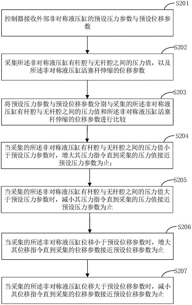
[0072] The controller 17 accepts the external pressure command and simultaneously calculates the real-time pressure values of the piston rod two chambers detected by the second pressure sensor 11 and the third pressure sensor 13 of the two chambers of the asymmetric hydraulic cylinder 15. If the calculated piston rod output of the asymmetric hydraulic cylinder 15 When the pressure value is less than the command pressure, the controller 17 issues an extension command to the driver 18, the driver 18 drives the servo motor 1 to rotate in the forward direction, and the servo motor 1 drives the two-way quantitative pump 2 to output oil at port A and absorb oil at port B, and the conventional accumulator 6 provides The oil suction flow rate at port 2B of the two-way quantitative pump, the electromagnetic ball valve 7 is energized, and the pressure oil at port 2A of the two-way quantitative ...
PUM
 Abstract
Description
Claims
Application Information
 - R&D
- Intellectual Property
- Life Sciences
- Materials
- Tech Scout
- Unparalleled Data Quality
- Higher Quality Content
- 60% Fewer Hallucinations
Browse by: Latest US Patents, China's latest patents, Technical Efficacy Thesaurus, Application Domain, Technology Topic, Popular Technical Reports.
© 2025 PatSnap. All rights reserved.Legal|Privacy policy|Modern Slavery Act Transparency Statement|Sitemap|About US| Contact US: help@patsnap.com


