Dual thrust bearing for a turbocharger

A thrust bearing and double thrust technology, applied in the direction of rotating bearings, bearings, turbine/propulsion device lubrication, etc., can solve problems such as time-consuming repair or replacement, damage to the bearing mounting surface, and expensive central housing

Inactive Publication Date: 2016-06-29
ELECTRO-MOTIVE DIESEL
View PDF1 Cites 2 Cited by
  • Summary
  • Abstract
  • Description
  • Claims
  • Application Information

AI Technical Summary

Problems solved by technology

The unequal thrust loads on the two thrust surfaces of the bearing of the '184 patent would deflect the bearing relative to the axis of rotation of the bearing, which in turn would constrain the rotation of the shaft within the journal of the bearing
Furthermore, due to the direct attachment of the '184 patent's one-piece bearings to the center housing, a typical rotor failure could damage both the bearings and the mounting surfaces of the center housing, requiring costly and time-consuming repair or replacement of the center housing

Method used


Image

  • Dual thrust bearing for a turbocharger
  • Dual thrust bearing for a turbocharger
  • Dual thrust bearing for a turbocharger

Examples


Embodiment Construction

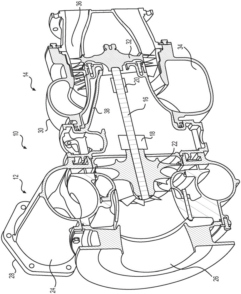
[0017] figure 1 An exemplary embodiment of a turbocharger 10 is shown. Turbocharger 10 may be used with an engine (not shown) of a machine performing some type of operation related to an industry such as railroading, shipping, power generation, mining, construction, agriculture, or another industry known in the art. Such as figure 1 As shown, turbocharger 10 may include a compressor stage 12 and a turbine stage 14 . Shaft 16 may extend between compressor stage 12 and turbine stage 14 . Shaft 16 may be supported by one or more bearing assemblies 18 and / or bearings 20 . Compressor stage 12 may embody a fixed geometry compressor wheel 22 connected to shaft 16 and configured to compress air received from the environment to a predetermined pressure level prior to entering the engine for combustion. Air may enter compressor housing 24 via compressor inlet 26 and exit compressor housing 24 via compressor outlet 28 . As the air moves through compressor stages 12 , compressor whee...


PUM


Abstract

A dual thrust bearing is disclosed. The dual thrust bearing may have a shell. The shell may extend from a compressor end to a turbine end opposite the compressor end. The shell may have a shell bore extending from the compressor end to the turbine end. The shell bore may be configured to receive a journal bearing. The shell may also have a first thrust bearing face disposed adjacent the compressor end. In addition, the shell may have a second thrust bearing face disposed adjacent the turbine end.

Description

technical field [0001] The present invention relates generally to dual thrust bearings, and more particularly to dual thrust bearings for turbochargers. Background technique [0002] Internal combustion engines such as diesel engines, gasoline engines or natural gas engines employ turbochargers to deliver compressed air into the engine for combustion. A turbocharger compresses the air flowing into the engine, which helps force more air into the engine's combustion chambers. The increased air supply allows for increased fuel combustion in the engine's combustion chambers, resulting in increased power output from the engine. [0003] A typical turbocharger includes a shaft, a turbine wheel connected to one end of the shaft, a compressor wheel connected to the other end of the shaft, and bearings to support the shaft. A separate housing connected to each other houses the compressor wheel, turbine wheel and bearings. The exhaust from the engine expands over and spins the turb...

Claims


Application Information

Patent Timeline
Patent Type & Authority Applications(China)
IPC IPC(8): F16C17/10F16C35/02F02C7/06F02C6/12
CPCF04D25/024F04D29/0513F04D29/624F16C2360/24F16C17/10
Inventor G·R·什维赫拉A·R·维德迈尔R·雷克萨维尔
Owner ELECTRO-MOTIVE DIESEL
Why Eureka
Try Eureka