
Quick joint with pressure limit function

A fast and functional technology, applied in mechanical equipment, couplings, etc., can solve the problems of motor casing breakage, motor shaft seal damage, scrapping, etc., and achieve the effect of simplifying the oil circuit

Active Publication Date: 2016-06-29
XCMG CONSTR MACHINERY
View PDF7 Cites 1 Cited by
  • Summary
  • Abstract
  • Description
  • Claims
  • Application Information

AI Technical Summary

Problems solved by technology

[0003] Taking the use of motors and hydraulic cylinders as an example, when the hydraulic motor is working, the housing needs a separate drain oil circuit to lead back to the oil tank; however, after the components are disassembled, this part of the oil circuit also needs to be disconnected through the quick connector, so that the motor housing A closed cavity is formed inside the body, hydraulic pipeline and quick connector. Due to the large volume expansion coefficient of the hydraulic oil, when the ambient temperature rises high, the hydraulic oil in the closed cavity will expand and cause the cavity to The oil pressure rises, causing the motor shaft seal to be damaged or even the motor casing to be broken
For crawler cranes, most of the hydraulic cylinders are carried by the large cavity, and the pressure is maintained through the load holding valve. After the load holding valve, the reversing valve is connected to the oil tank indirectly through the quick joint; after the hydraulic cylinder is disassembled and transported, both the large cavity and the small cavity pass through The quick connector is closed; if the ambient temperature rises, the hydraulic oil in the large and small oil chambers of the cylinder will expand, causing the pressure to rise. Because there is a large difference in the area of ​​the large and small chambers, the large chamber bears a large force and directly acts on the small chamber, so the pressure in the small chamber It is often several times higher than that of the large cavity (the ratio of the effective area of ​​the large cavity to the area of ​​the small cavity), which causes the hydraulic oil in the small cavity to release pressure through the internal sealing ring of the cylinder or the seal of the guide sleeve, resulting in failure of the cylinder seal or even cylinder expansion. big and totally scrapped

Method used


Image

  • Quick joint with pressure limit function
  • Quick joint with pressure limit function
  • Quick joint with pressure limit function

Examples


Embodiment Construction

[0018] The present invention will be further described below in conjunction with the accompanying drawings. The following examples are only used to illustrate the technical solution of the present invention more clearly, but not to limit the protection scope of the present invention.

[0019] In the prior art, the use of the motor is taken as an example. At present, the pressure relief method of the motor casing is to connect a check valve or overflow valve with a certain back pressure in parallel on the quick-plug oil circuit. After the quick-plug is disconnected, the motor casing If the internal hydraulic oil pressure rises, the hydraulic oil can leak directly into the atmosphere through the parallel valve to form a pressure relief. Although the above scheme plays the same role, if the selected one-way valve or overflow valve is damaged, the hydraulic oil in the motor casing will not return to the oil tank through the pipeline during normal operation, but will pass through t...


PUM


Abstract

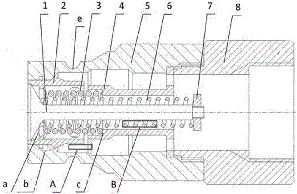
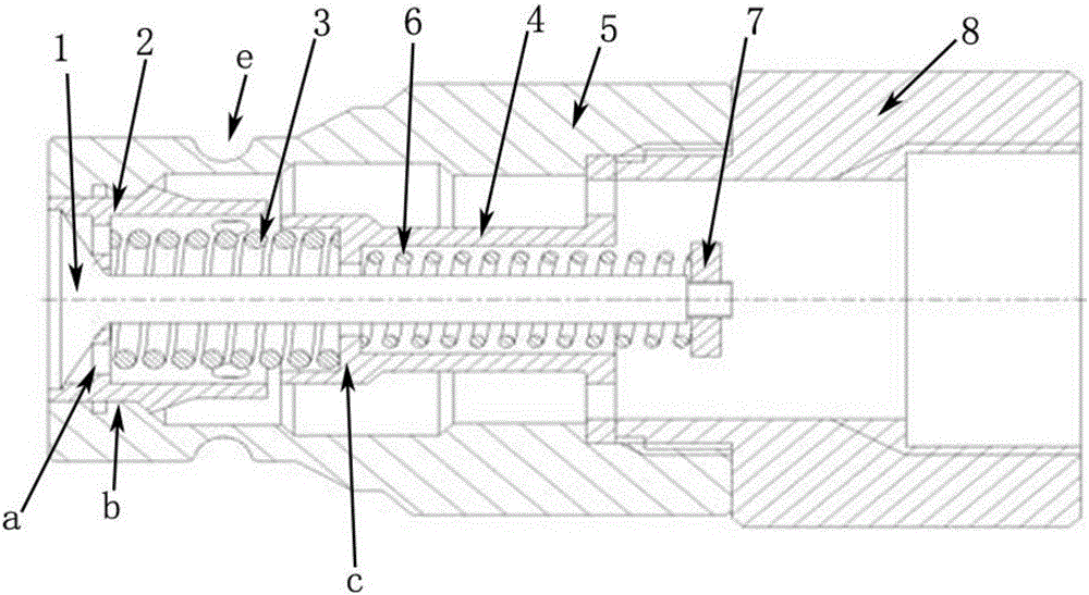
The invention discloses a quick joint with a pressure limit function. The quick joint is characterized by comprising a joint body, a base, a valve element arranged in the joint body, a first spring, a second spring, a valve sleeve and a valve base, wherein the valve element, the valve sleeve, the second spring and a nut constitute an overflow valve; the first spring is coaxially arranged in the valve sleeve and the valve base and supplies thrust to the valve sleeve; the second spring is coaxially arranged in the valve base and the valve sleeve; the valve sleeve and the valve base are respectively provided with steps used for propping against two ends of the first spring and one end of the second spring; the valve base is fixed by virtue of the joint body and the base; the valve sleeve slides under guidance of the external cylindrical surface of the valve base. The quick joint has the beneficial effects that the overflow valve is directly integrated in the quick joint, so that additional elements are avoided, an oil way of a hydraulic system is simplified, an element protection device is not needed to be additionally arranged, and the quick joint has an antipollution effect.

Description

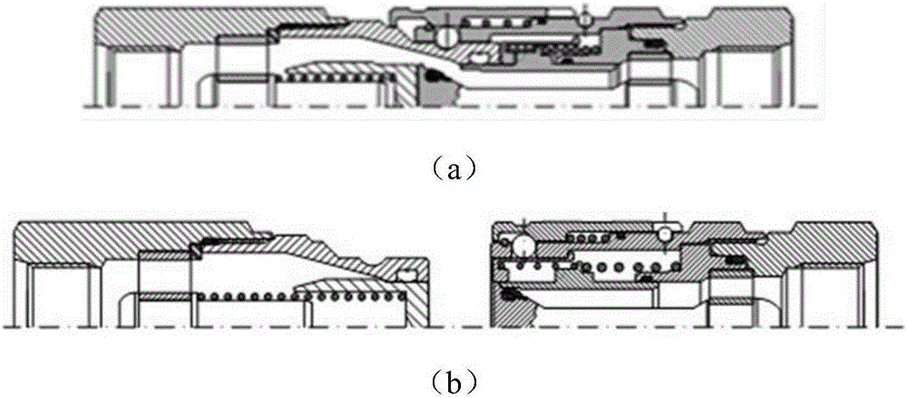
technical field [0001] The invention relates to a quick joint, in particular to a quick joint with pressure-limiting function. Background technique [0002] Taking large-tonnage crawler cranes as an example, the main parts of the machine need to be disassembled and transported in separate parts when the whole machine is transported, which makes the hydraulic pipelines laid inside the parts to be disassembled together. It is connected with quick connectors that are more convenient to disassemble and install, and make the separated two parts of the oil circuit form their own closed oil chambers, such as figure 1 (a) (b) shown. [0003] Taking the use of motors and hydraulic cylinders as an example, when the hydraulic motor is working, the housing needs a separate drain oil circuit to lead back to the oil tank; however, after the components are disassembled, this part of the oil circuit also needs to be disconnected through the quick connector, so that the motor housing A clo...

Claims


Application Information

Patent Timeline
Patent Type & Authority Applications(China)
IPC IPC(8): F16L37/40
CPCF16L37/40
Inventor 李为民孙影孟进军
Owner XCMG CONSTR MACHINERY
Learn More