
Heat accumulating type organic waste gas incinerator and running method thereof

A technology of organic waste gas and operation method, which is applied in the field of environmental protection and air pollution control, can solve the problems of low removal rate, sudden drop in the flow rate of the treatment system, damage removal rate, etc., and achieve a simple system, ensure continuity, and high utilization rate Effect

Inactive Publication Date: 2016-06-29
北京矿大节能科技有限公司
View PDF0 Cites 8 Cited by
  • Summary
  • Abstract
  • Description
  • Claims
  • Application Information

AI Technical Summary

Problems solved by technology

The incinerator with two regenerators has the problem that the waste gas is directly discharged when the direction is reversed, which causes the damage removal rate to decrease, and the flow rate of the treatment system drops sharply when the direction is reversed.
The three-regenerator incinerator adds a purge system to improve the damage removal rate when the direction is reversed, but there is still the problem of a sudden drop in the flow rate of the treatment system when the direction is reversed.
The multi-regenerator rotary reversing incinerator solves the problem of low damage removal rate and sudden drop in flow rate of the treatment system during reversing, but it also brings high manufacturing cost, high failure rate and yearly increase in valve leakage of the rotary reversing valve, resulting in damage removal rate reduction etc.

Method used


Image

  • Heat accumulating type organic waste gas incinerator and running method thereof
  • Heat accumulating type organic waste gas incinerator and running method thereof

Examples


Embodiment approach

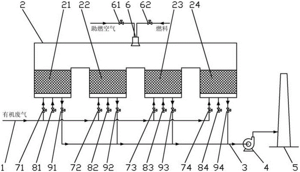
[0023] figure 1 As an embodiment of the present invention, a regenerative organic waste gas incinerator includes: organic waste gas main pipe 1, intake control valve group, incinerator body 2, regenerator, purge control valve group, exhaust control Valve group, flue gas main pipe 3, induced draft fan 4, chimney 5, starting burner 6. A plurality of parallel regenerators are arranged in the incinerator body, the organic waste gas main pipe 1 is connected in parallel with the exhaust gas inlet of each regenerator through the intake control valve group, and the flue gas outlet of each regenerator is connected with the exhaust gas control valve group. The flue gas main pipes 3 are connected in parallel, and the air inlet of each regenerator communicates with the atmospheric environment through the purge control valve group. The flue gas main pipe 3 is connected to the air inlet of the induced draft fan 4 , and the air outlet of the induced draft fan 4 is connected to the chimney 5...


PUM


Abstract

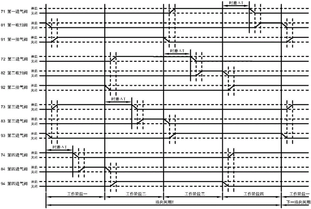
The invention belongs to the technical fields of environmental protection and air pollution control, and relates to a regenerative organic waste gas incinerator and an operation method thereof, which are used for treating organic waste gas containing low-concentration volatile organic compounds with high efficiency and low cost. The innovation of the present invention lies in: a regenerative organic waste gas incinerator and its operation method, in which four identical regenerators are arranged in the incinerator body; each regenerator is connected to the organic waste gas through an air intake control valve Exhaust gas main pipe connection; each regenerator is connected to the flue gas main pipe through an exhaust control valve; each regenerator is connected to the atmospheric environment through a purge control valve; each valve operates in sequence according to a specific control sequence , to achieve low-cost and high-efficiency treatment of organic waste gas, while ensuring the continuity of organic waste gas and ensuring that there is no direct discharge of untreated organic waste gas. The purging system has no additional equipment and pipelines, and the system is simple.

Description

technical field [0001] The invention belongs to the technical fields of environmental protection and air pollution control, and relates to a regenerative organic waste gas incinerator and an operation method thereof, which are used for treating organic waste gas containing low-concentration volatile organic compounds with high efficiency and low cost. Background technique [0002] Currently used regenerative organic waste gas incinerators have several structural forms, including two regenerators, three regenerators and multiple regenerators with rotary reversing. The incinerator with two regenerators has the problems of direct discharge of waste gas during reversing, which causes a decrease in the destruction removal rate, and a sudden drop in the flow rate of the treatment system during reversing. The three-regenerator incinerator increases the purge system to improve the damage removal rate during the reversing, but there is still the problem of a sudden drop in the flow r...

Claims


Application Information

Patent Timeline
Patent Type & Authority Applications(China)
IPC IPC(8): F23G7/06F23K5/00
CPCF23G7/06F23K5/002
Inventor 王建学萧琦孟杰王杏坤索金莉
Owner 北京矿大节能科技有限公司
Learn More