A fuel-cooled evaporator tube structure

An evaporating tube and cooling type technology, which is applied in the field of fuel-cooled evaporating tube structure, can solve the problems of long flame area, overheating and smoking at the outlet section of the evaporating tube of the evaporating tube, so as to improve the preheating degree of fuel and improve the evaporation rate. The effect of premixing and improving service life

Active Publication Date: 2018-02-16
INST OF ENGINEERING THERMOPHYSICS - CHINESE ACAD OF SCI +1
View PDF7 Cites 0 Cited by
  • Summary
  • Abstract
  • Description
  • Claims
  • Application Information

AI Technical Summary

Problems solved by technology

[0003] The commonly used evaporator tube technology designs the fuel nozzle and the evaporator tube independently. The fuel directly enters the gas flow channel of the evaporator tube without passing through the heat exchange on the wall of the evaporator tube in advance. The wall of the evaporator tube is not cooled by fuel oil, resulting in Overheating or even ablation. At the same time, this method makes the fuel preheating effect poor. When entering the air flow channel, the temperature is low and the atomization is poor, resulting in a longer flame zone, smoke, and a decrease in combustion efficiency and flameout performance.

Method used


Image

  • A fuel-cooled evaporator tube structure
  • A fuel-cooled evaporator tube structure
  • A fuel-cooled evaporator tube structure

Examples


Embodiment Construction

[0025] The present invention will be further described in detail below in conjunction with the examples, the following examples are explanations of the present invention and the present invention is not limited to the following examples.

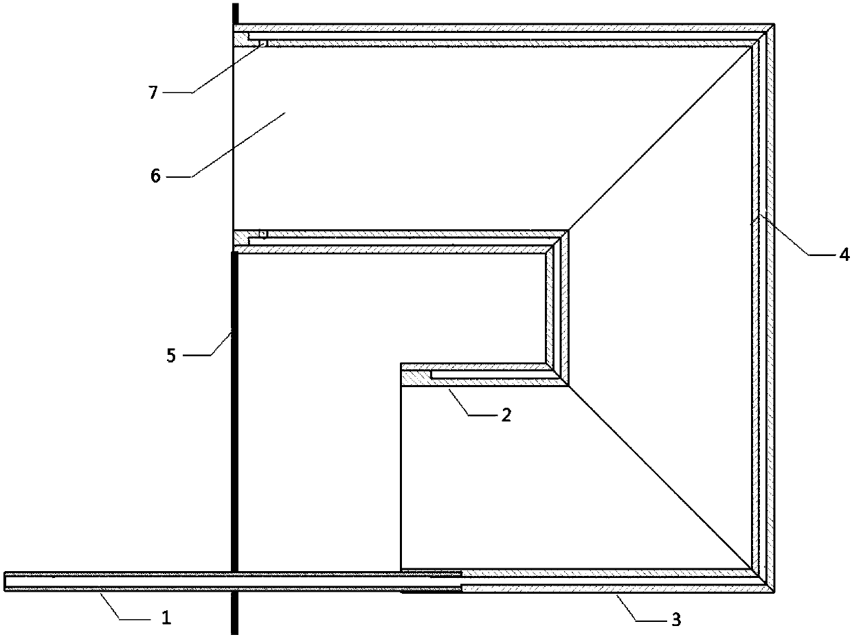
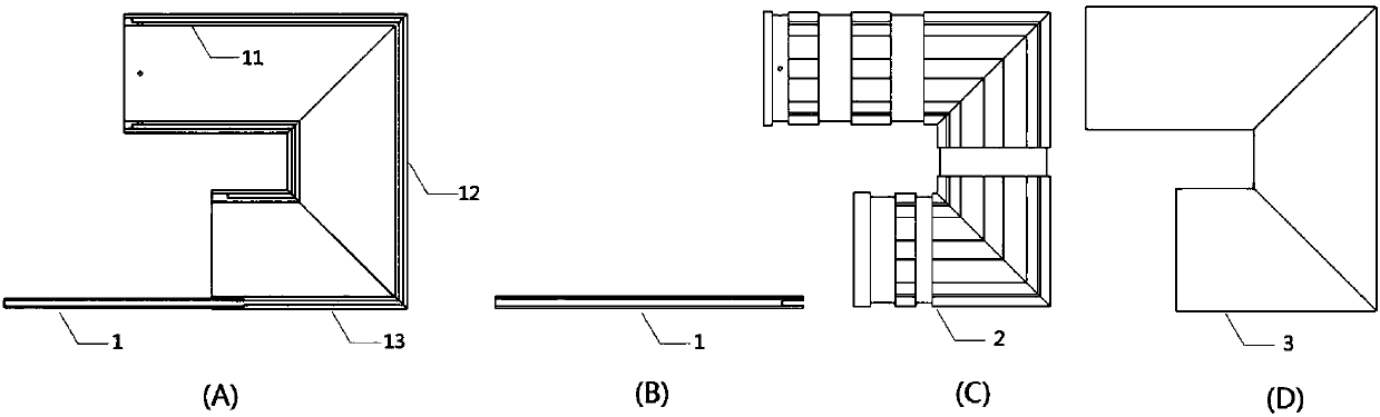
[0026] Such as Figures 1 to 6 As shown, the fuel-cooled evaporating tube structure of the present invention is suitable for combustion chambers of gas turbines or other engines, and includes a fuel inlet tube 1 and an evaporating tube, and the evaporating tube includes an inlet section 11, a transition section 12 and an outlet section 13 connected in sequence The evaporation tube is fixedly arranged on the wall surface 5 of the combustion chamber through its inlet section 11, and there is a certain distance between the outer end of the outlet section 13 of the evaporation tube and the wall surface 5 of the combustion chamber.

[0027] The wall surface of the evaporating tube is from the inside to the outside in order of the evaporating tube...


PUM


Abstract

The invention relates to a fuel-cooled type evaporating pipe structure. The evaporating pipe structure is applicable to engines and combustion chamber components of other burners, a closed fuel cooling cavity is formed between an evaporating pipe inner sleeve and an evaporating pipe outer sleeve, a fuel inlet pipe extends into the fuel cooling cavity in the outlet section position of the evaporating pipe, at least one row of fuel nozzles evenly distributed in the circumferential direction are arranged along the inlet section of the evaporating pipe inner sleeve, grooves communicating with one another are formed in the outer surface of the evaporating pipe inner sleeve, and fuel is delivered to the outlet section from the inlet section of the fuel cooling cavity along the grooves and is sprayed into the evaporating pipe at the inlet section. According to the structure, the fuel arrives at the fuel nozzles at the inlet section of the evaporating pipe from the inner cavity of the outlet section of the evaporating pipe and cools the wall surface of the evaporating pipe, and thermal state ablation protection of the evaporating pipe is completed; each way of fuel is preheated independently, the preheating degree of the fuel is increased, and the evaporating and premixing effect of the fuel is enhanced. By the aid of the overall design, cooling protection of the evaporating pipe is realized, and the service life is prolonged; high-intensity preheating of the fuel is realized, and the evaporating and premixing degree is increased.

Description

technical field [0001] The invention belongs to the technical field with combustion characteristics, especially the technical field of gas turbine combustion chambers, and in particular relates to a fuel-cooled evaporation tube structure suitable for gas turbine combustion chambers. Background technique [0002] At present, gas turbines using evaporator tube combustion technology have been widely used. For example, AMT in the Netherlands, Rolls-Royce in the UK, Artesjet, etc. have a series of products. The structure of a certain type of aviation gas turbine combustor is as follows: figure 2 As shown, it consists of the front wall, inner wall, outer wall, evaporation tube and fuel nozzle of the flame tube. The evaporator tube is located in the combustion high-temperature zone. During long-term use, it is found that the outlet section and the transition section of the evaporator tube are overheated or even ablated, which seriously restricts the service life. [0003] The co...

Claims


Application Information

Patent Timeline
Patent Type & Authority Patents(China)
IPC IPC(8): F23R3/32
CPCF23R3/32F23R2900/03343
Inventor 穆勇刘存喜刘富强杨金虎阮昌龙徐纲
Owner INST OF ENGINEERING THERMOPHYSICS - CHINESE ACAD OF SCI
Why Eureka
Try Eureka