A water collection and return combined well structure with the filter tube moving down

A filter tube and well structure technology, which is applied in the field of water source heat pumps, can solve the problems of reducing the filtering effect, soil loss in the filter material layer, increasing construction and operating costs, etc., and achieve the effect of improving the filtering effect

Active Publication Date: 2018-05-15
辽宁申和新能源科技有限公司
View PDF8 Cites 0 Cited by
  • Summary
  • Abstract
  • Description
  • Claims
  • Application Information

AI Technical Summary

Problems solved by technology

The outlet well or return well is an indispensable part of water source thermal energy technology; the existing technology generally uses multiple separate water collection wells and return wells, which inevitably causes an increase in construction and operation costs; in addition, the existing Since the backwater well has no sand blocking structure, the sediment in the system operation will deposit on the filter material layer of the backwater wellhead, causing the filter material layer of the backwater wellhead to fail. In addition, because there is no sand control edge, the bottom of the inspection well is full of silt , workers inspection and construction are very difficult
[0003] The underground structure is generally divided into clay layer, aquifer layer and rock layer from top to bottom. The existing water collection well generally sets the filter tube in the aquifer layer, and due to the scouring effect of the water flow during operation, the filter material layer on both sides of the filter tube The soil is continuously lost, resulting in Figure 4 The huge cavity 21 in the cavity, the sand in the cavity is mixed with the filter material, which reduces the filtering effect, and the filter material needs to be continuously replenished, which undoubtedly increases the operating cost and reduces the efficiency of the unit

Method used


Image

  • A water collection and return combined well structure with the filter tube moving down
  • A water collection and return combined well structure with the filter tube moving down
  • A water collection and return combined well structure with the filter tube moving down

Examples


Embodiment Construction

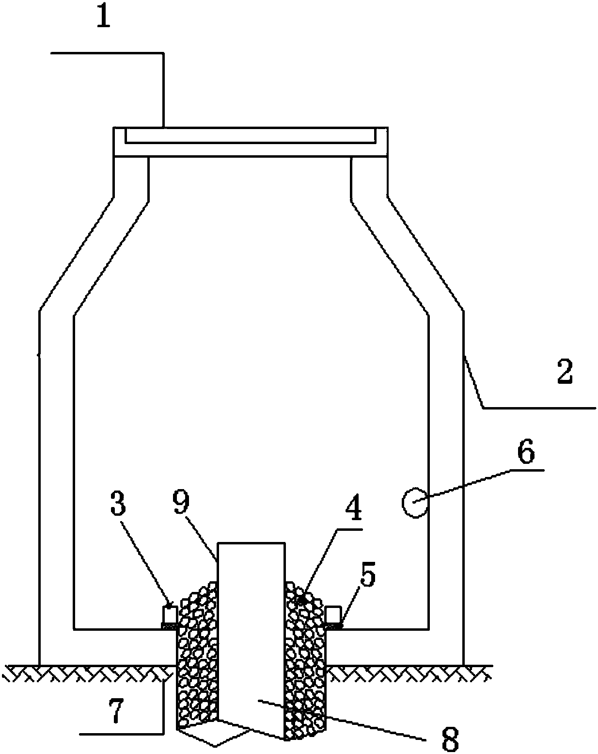
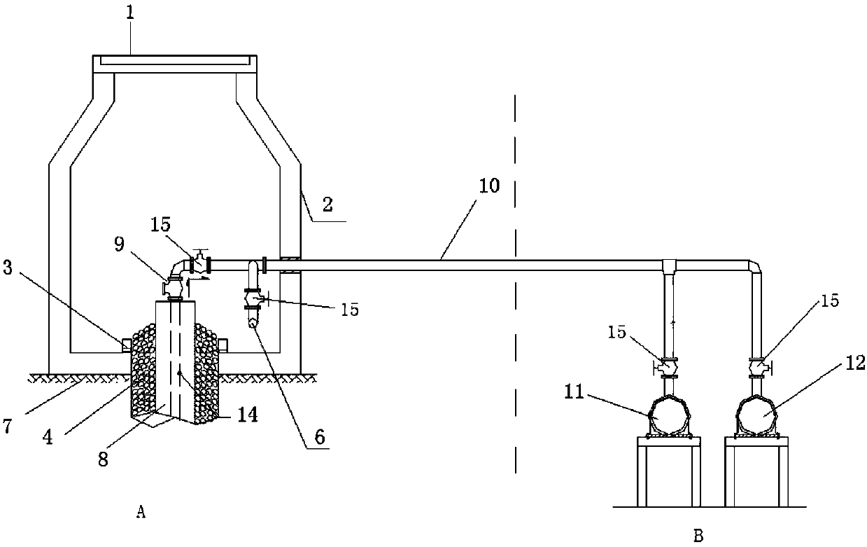
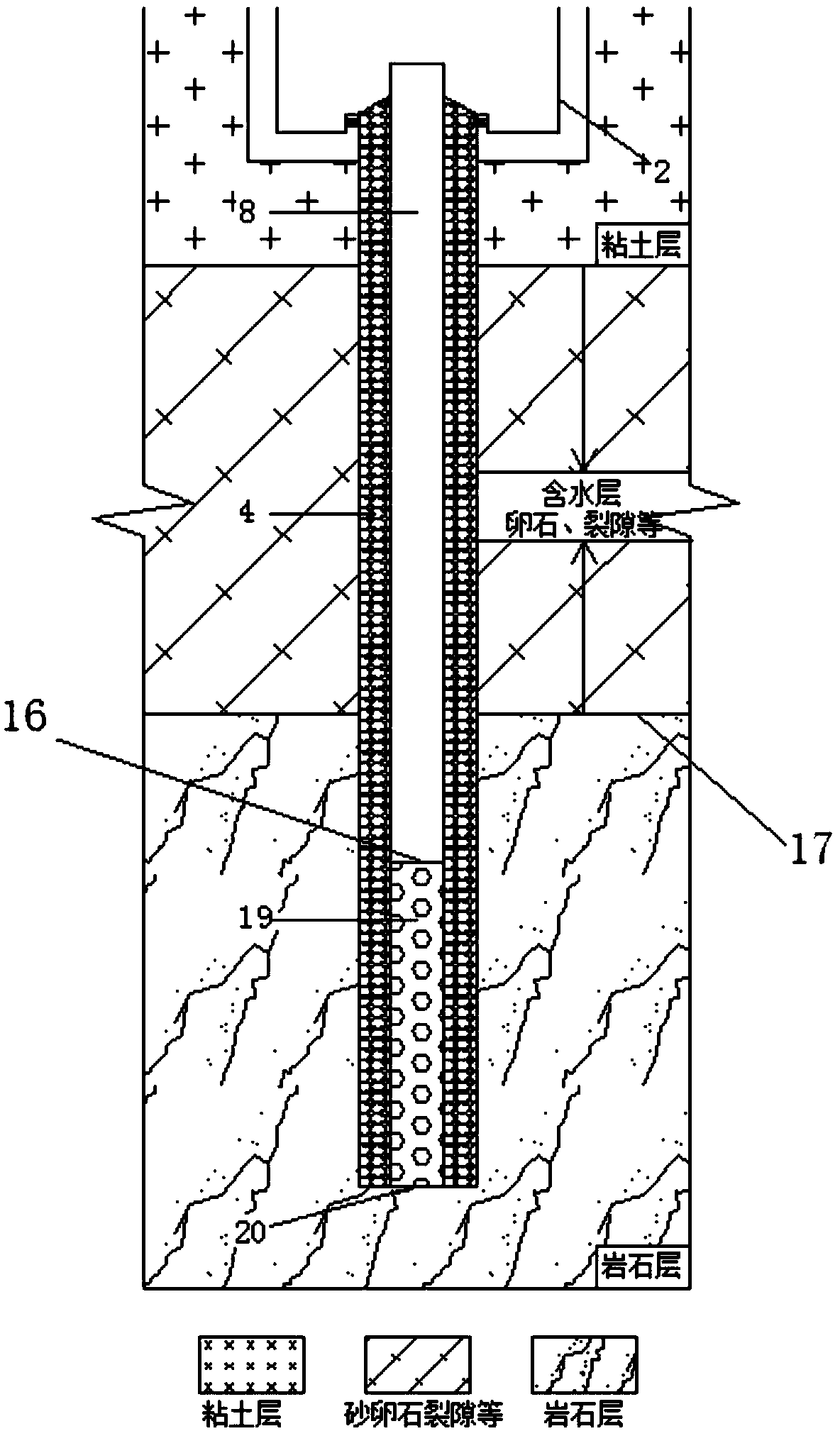
[0016] The present invention is specifically described below in conjunction with accompanying drawing, as Figure 1-Figure 4 As shown, the present invention includes an inspection well 2, and the inspection well 2 is arranged on the original soil layer 7; The outer side is the filter material layer 4; the water-lifting pipe 14 is inserted into the well pipe and connected with the submersible pump; the water-lifting pipe 14 is connected with the main pipeline 10 through the one-way valve 9 and the valve 15; the return pipe 6 is arranged at the lower end of the detection well, and the return pipe 6 Connect with the main pipeline 10 through the valve 15; the main pipeline 10 is respectively connected with the water collector 11 and the water distributor 12 through the valve 15; The top 16 is lower than the top 17 of the rock formation.

[0017] The valve 15 between the water lifting pipe and the main pipeline, the valve 15 between the water return pipe and the main pipeline, the...


PUM


Abstract

The invention discloses a water collection and return well structure in which the filter tube is moved downward, which includes an inspection well, the inspection well is arranged on the original soil layer; the top of the inspection well is a well cover, and a through hole is left at the bottom of the well. Set the well pipe; the outside of the well pipe is the filter material layer; the water pipe is inserted into the well pipe and connected to the submersible pump; the water pipe is connected to the main pipe through a one-way valve and the valve; the return pipe is set at the lower end of the detection well, and the return pipe passes through the valve It is connected with the main pipeline; the main pipeline is respectively connected with the water collector and the water distributor through valves; the lower end of the well pipe is a filter pipe, which is set at the bottom of the well, and the top of the filter pipe is lower than the top of the rock layer. Since the filter pipe is arranged at the bottom of the well and corresponds to the rock layer, the filter material layer will not collapse and form a cavity; in addition, since the distance of water passing through the filter material layer is greatly increased compared with the existing technology, the filtration rate is improved. Effect.

Description

technical field [0001] The invention relates to the technical field of water-source heat pumps, in particular to a water-collecting-water-combining-well structure. Background technique [0002] Water source heat pump technology is a low-temperature low-level thermal energy resource formed by using solar energy and geothermal energy absorbed by shallow water sources on the earth's surface, and adopts the principle of heat pumps to realize the transfer of low-level thermal energy to high-level thermal energy through a small amount of high-level electrical energy input. The outlet well or return well is an indispensable part of water source thermal energy technology; the existing technology generally uses multiple separate water collection wells and return wells, which inevitably causes an increase in construction and operation costs; in addition, the existing Since the backwater well has no sand blocking structure, the sediment in the system operation will deposit on the filte...

Claims


Application Information

Patent Timeline
Patent Type & Authority Patents(China)
IPC IPC(8): F25B30/06F24T10/00
CPCY02E10/10
Inventor 滕飞
Owner 辽宁申和新能源科技有限公司
Why Eureka
Try Eureka