
Controlled fragment with warhead shell function

A warhead and fragment technology, applied in the field of prefabricated fragments, can solve the problems of affecting the flight speed and flight trajectory of prefabricated fragments, affecting the effectiveness of prefabricated fragments, reducing the stress of prefabricated fragments, etc., so as to reduce flight resistance, increase kinetic energy, and reduce speed. effect of loss

Inactive Publication Date: 2016-06-29
杨民让
View PDF7 Cites 4 Cited by
  • Summary
  • Abstract
  • Description
  • Claims
  • Application Information

AI Technical Summary

Problems solved by technology

[0002] Currently as Figure 4 The structure of the prefabricated fragment warhead shown is that a steel structure casing is provided on the periphery of the grain, and prefabricated fragments are arranged on the inside or outside of the steel structure casing; in this way, after the explosion of the grain, part of the force is used to push away the steel structure casing, and the other part acts on the prefabricated fragments. The stress on the prefabricated fragment is relatively reduced, which affects its destructive force when it reaches the target
At the same time, when the explosive column explodes, the steel shell fragments will affect the flight speed and flight trajectory of the prefabricated fragments, seriously affecting the effectiveness of the prefabricated fragments
[0003] The traditional prefabricated fragments are all square after the explosion, and the air resistance they encounter during the flight is large, which reduces the penetration of the target

Method used


Image

  • Controlled fragment with warhead shell function
  • Controlled fragment with warhead shell function
  • Controlled fragment with warhead shell function

Examples


Embodiment Construction

[0018] The following will clearly and completely describe the technical solutions in the embodiments of the present invention with reference to the accompanying drawings in the embodiments of the present invention. Obviously, the described embodiments are only some, not all, embodiments of the present invention. Based on the embodiments of the present invention, all other embodiments obtained by persons of ordinary skill in the art without creative efforts fall within the protection scope of the present invention.

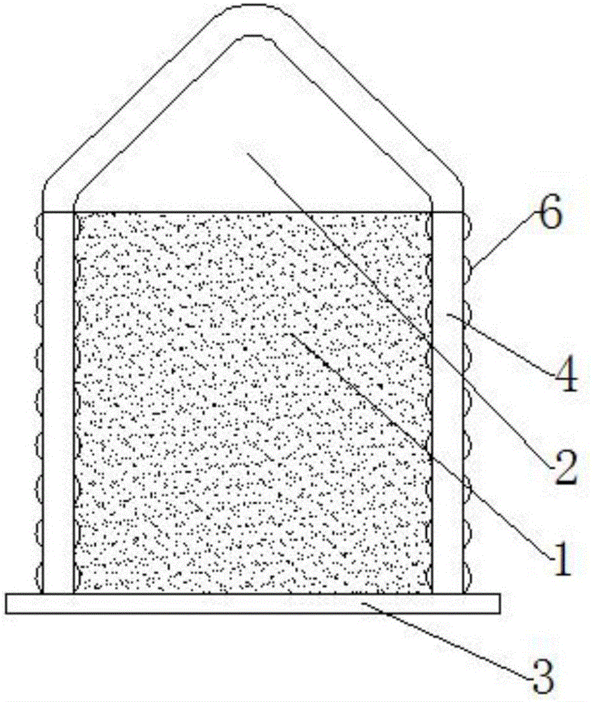
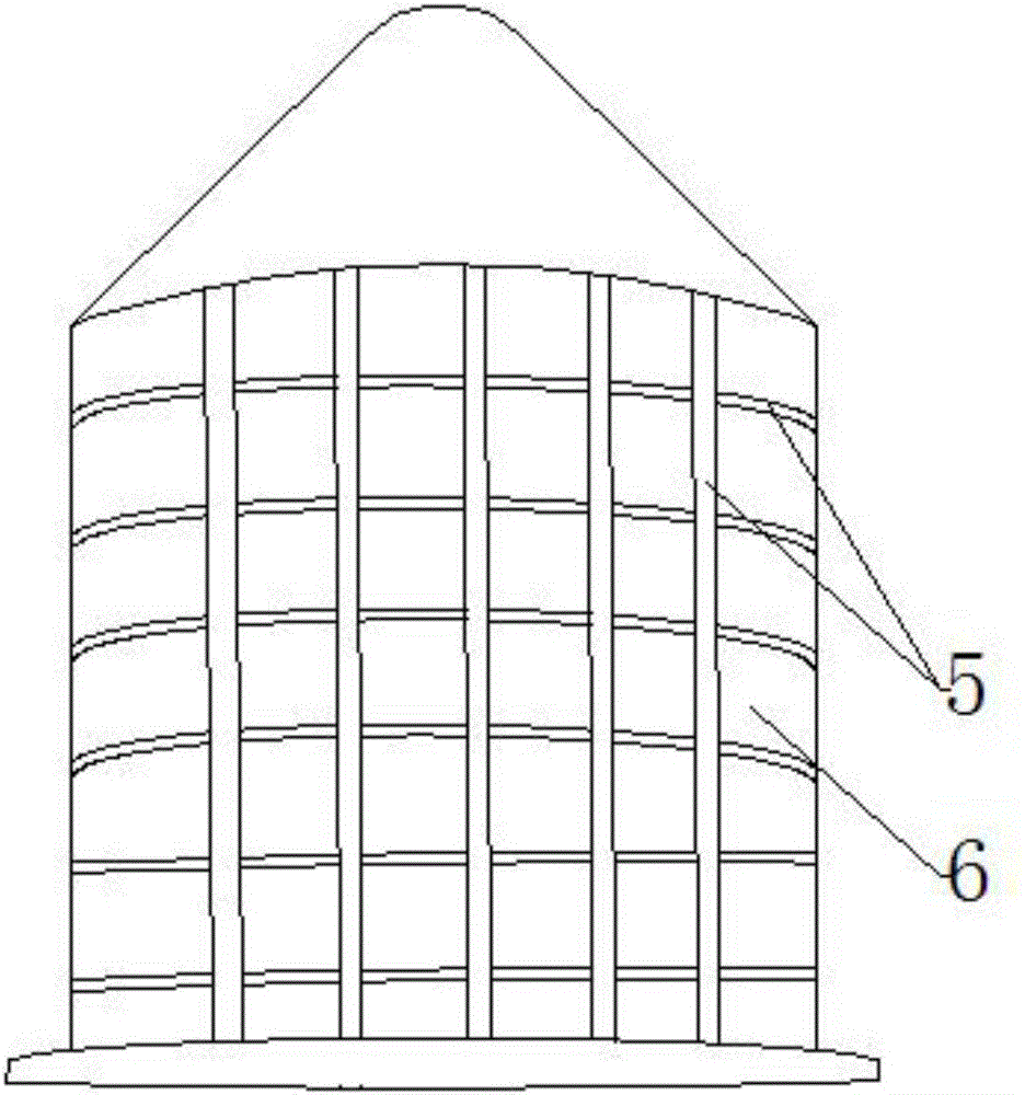
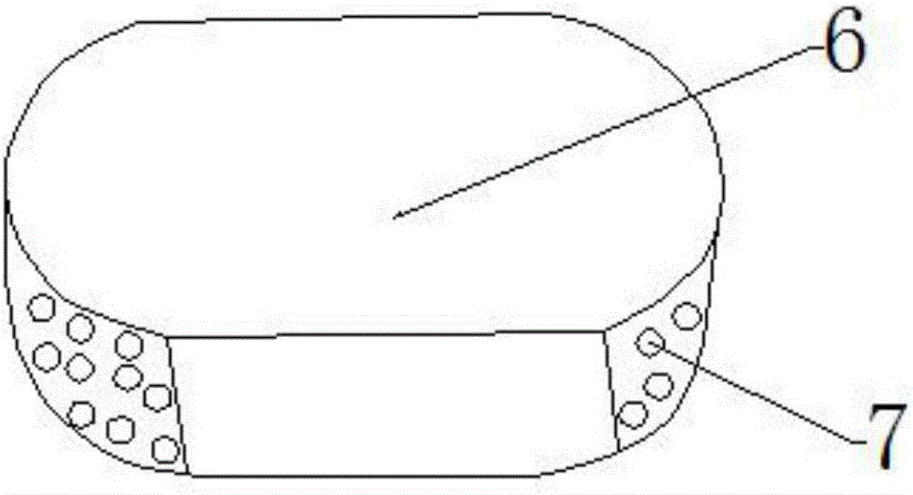
[0019] Such as Figure 1~3 Shown is a prefabricated fragment with the function of the warhead shell. The warhead shell includes a powder column 1, a conical protective cover 2 and a seal 3 located at the tail of the powder column 1. A cylindrical prefabricated fragment is set outside the powder column 1. 4. The inner and outer surfaces of the prefabricated fragment 4 are provided with partition grooves 5 equidistant horizontally and vertically, with a solid structu...


PUM


Abstract

The invention discloses a controlled fragment with a warhead shell function. A warhead shell comprises a grain, a conical protection cover and a sealing part located on the tail of the grain; the grain is sleeved with a columnar controlled fragment body, partitioning troughs are transversely and longitudinally formed in the inner surface and the outer surface of the controlled fragment body at equal distances, and a solid body is arranged in the middle portion; the controlled fragment body is divided into a plurality of partitioning bodies through the partitioning troughs; and the tow ends of the partitioning bodies are in a streamline shape. The controlled fragment has the beneficial effects that the stress of the grain to the controlled fragment body is effectively increased, speed losses of the partitioning bodies in the flying process are reduced, the kinetic energy of the partitioning bodies reaching the target point becomes large, the penetrating power of the partitioning bodies to a target is high, and the effectiveness of the partitioning bodies is improved.

Description

technical field [0001] The invention relates to a prefabricated fragment with the function of a warhead shell. Background technique [0002] Currently as Figure 4 The structure of the prefabricated fragment warhead shown is that a steel structure casing is provided around the grain, and prefabricated fragments are arranged on the inside or outside of the steel structure casing; in this way, after the explosion of the grain, part of the force is used to push away the steel structure casing, and the other part acts on the prefabricated fragments. The stress on the prefabricated fragment is relatively reduced, which affects its destructive force when it reaches the target. At the same time, when the explosive column explodes, the steel shell fragments will affect the flight speed and flight trajectory of the prefabricated fragments, seriously affecting the effectiveness of the prefabricated fragments. [0003] The traditional prefabricated fragments are all square after the e...

Claims


Application Information

Patent Timeline
Patent Type & Authority Applications(China)
IPC IPC(8): F42B12/10
CPCF42B12/10
Inventor 杨民让
Owner 杨民让
Learn More