Circuit board plug hole method and circuit board

A circuit board and plug hole technology, which is applied to printed circuit components, electrical connection printed components, and printed component electrical connection formation. The effect of reducing production cost and improving plug hole quality

Active Publication Date: 2018-12-28
NEW FOUNDER HLDG DEV LLC +1
View PDF3 Cites 0 Cited by
  • Summary
  • Abstract
  • Description
  • Claims
  • Application Information

AI Technical Summary

Problems solved by technology

In this method, although the vacuum plugging machine can fully meet the requirements of back drilling 2 plug holes, and vacuum the inside of the through hole to eliminate air bubbles, the cost of vacuum plugging is high, and selective plugging is not possible, so two drillings are required Process for remaining non-resin plugged vias
This approach adds to the process while wasting costs

Method used


Image

  • Circuit board plug hole method and circuit board
  • Circuit board plug hole method and circuit board
  • Circuit board plug hole method and circuit board

Examples


Embodiment Construction

[0035] In order to understand the above-mentioned purpose, features and advantages of the present invention more clearly, the present invention will be further described in detail below in conjunction with the accompanying drawings and specific embodiments. It should be noted that, in the case of no conflict, the embodiments of the present application and the features in the embodiments can be combined with each other.

[0036] In the following description, many specific details are set forth in order to fully understand the present invention. However, the present invention can also be implemented in other ways different from those described here. Therefore, the protection scope of the present invention is not limited by the specific details disclosed below. EXAMPLE LIMITATIONS.

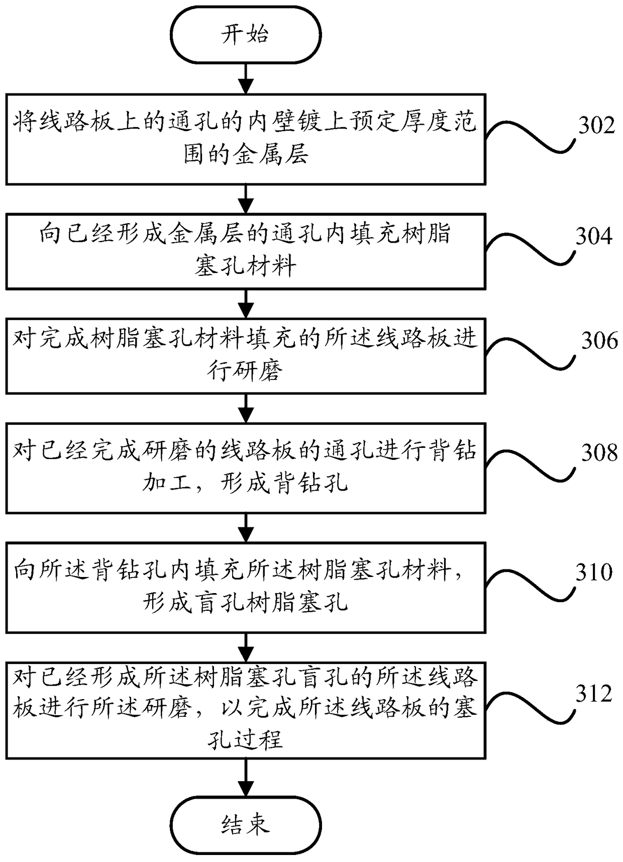
[0037] image 3 A schematic flowchart of a method for plugging holes in a circuit board according to an embodiment of the present invention is shown.

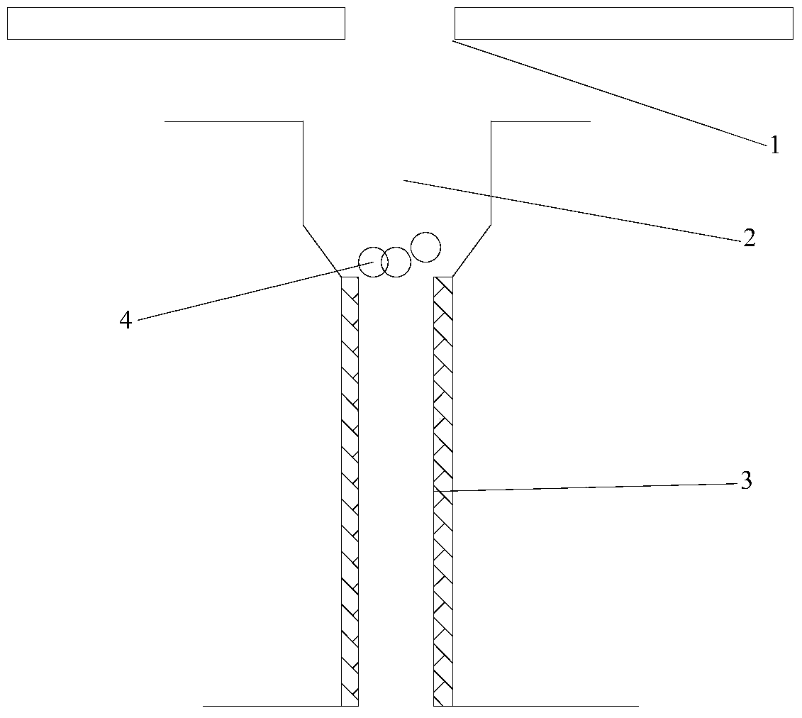
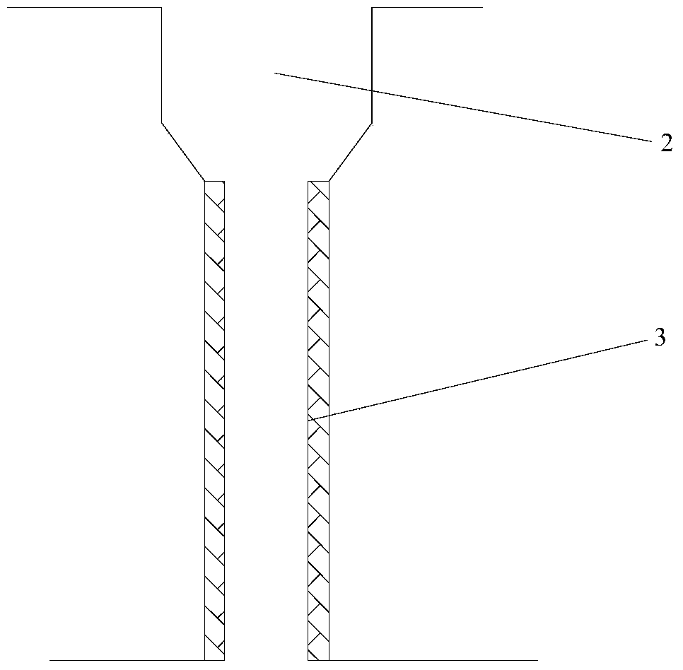
[0038] Such as image 3As shown, the circuit...


PUM


Abstract

The invention provides a circuit board hole filling method and a circuit board, and the method comprises the steps: plating an inner wall of a through hole on a circuit board with a metal layer with the preset thickness; placing a resin hole-filling material in the through hole with the formed metal layer; carrying out the grinding of the circuit board after the filling of the resin hole-filling material; carrying out the back drilling of the through hole of the circuit board after grinding, and forming a back drill hole; placing the resin hole-filling material in the back drill hole, and forming a blind resin jack; carrying out the grinding of the circuit board provided with the blind resin jack, so as to complete the hole-filling process of the circuit board. According to the technical scheme of the invention, the method can effectively reduce the residual bubbles after hole filling, improves the hole filling material, and reduces the production cost of a circuit board jack because a vacuum jack is avoided.

Description

technical field [0001] The invention relates to the technical field of circuit boards, in particular to a method for plugging holes in a circuit board and a circuit board. Background technique [0002] At present, in the circuit board processing in the industry, the market has a design requirement to use resin plug holes for back drilling and through holes. There are two current solutions: [0003] One is: if figure 1 As shown, before using the printing machine aluminum sheet 1 to plug the holes, the back drilling 2 is completed. The processing method is: electroplating → controlled depth drilling → aluminum sheet resin plug hole → resin grinding → follow-up process. The biggest problem with this method is that there will be air bubbles 4 remaining at the step between the back-drilled hole 2 and the through hole 3, which will cause the resin plug hole to not be full. [0004] The other is: if figure 2 As shown, after the back-drilled hole 2 is made, a vacuum plugging ma...

Claims


Application Information

Patent Timeline
Patent Type & Authority Patents(China)
IPC IPC(8): H05K1/11H05K3/40
Inventor 周斌
Owner NEW FOUNDER HLDG DEV LLC
Why Eureka
Try Eureka