
Process for filling resin in blind groove of printed circuit board (PCB)

A PCB board and blind groove technology, applied in the field of PCB blind groove plug resin technology, can solve the problems of unsatisfactory groove plug, production troubles, unclean grinding board, etc., and achieve the effect of improving quality and improving appearance quality.

Active Publication Date: 2016-06-29
DONGGUAN MEADVILLE CIRCUITS
View PDF4 Cites 12 Cited by
  • Summary
  • Abstract
  • Description
  • Claims
  • Application Information

AI Technical Summary

Problems solved by technology

[0003] 1) Due to the large volume of the blind groove, there will be a problem of insufficient oil under the silk screen;
[0004] 2) After the silk screen is screen printed, there will be a problem of pulling oil in the slot, which will cause the slot to be unsatisfactory;
[0005] 3) Since the bottom of the blind groove cannot form gas flow during the resin plugging process, it is easy to generate resin bubbles at the bottom;
[0006] 4) Due to the demand for large plug holes in the slot, there will be a disadvantage at the same time, that is, the accumulation of oil in the slot will cause the grinding plate to be dirty or over-grinding
[0007] It can be seen from the above that due to the influence of the existing production process, the quality of the product after production cannot be guaranteed, which increases the defect rate and scrap rate of the product, and brings many troubles to the production.

Method used


Image

  • Process for filling resin in blind groove of printed circuit board (PCB)
  • Process for filling resin in blind groove of printed circuit board (PCB)
  • Process for filling resin in blind groove of printed circuit board (PCB)

Examples


no. 1 example

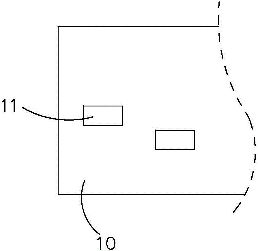
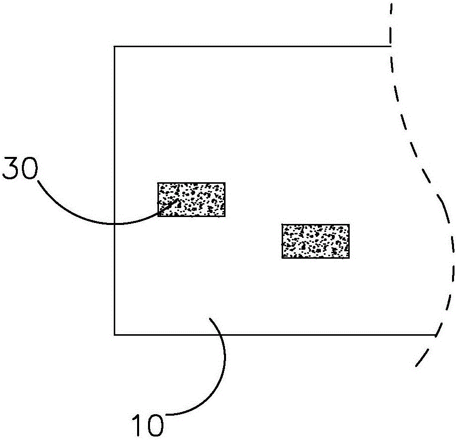
[0026] Such as Figure 1 to Figure 3 As shown, the present invention provides a PCB blind groove plugging resin process, which is used to fill the blind groove 11 of the PCB board 10 with resin ink 30. The following is the first embodiment of the present invention. The entire process of filling the blind groove 11 with resin ink 30 includes The following steps:

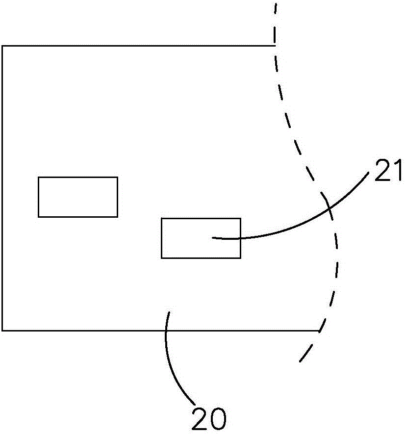
[0027] (1) Install the net, make a stencil 20 made of 0.15-0.20mm thick aluminum sheet and install it on the screen printing equipment. The stencil 20 is provided with an empty blind groove area oil drop hole 21, and the blind groove area falls The diameter of the oil hole 21 is larger than that of the blind groove 11 and forms a difference with it, specifically, the difference is 10-16mil;

[0028] (2), install backing plate, provide support platform for PCB board 10;

[0029] (3), the upper board, the PCB board 10 is placed on the backing board, and the opening part of the blind groove 11 of the PCB board 10 faces ...


PUM


Abstract

A processing for filling resin in a blind groove of a printed circuit board (PCB) is used for filling resin ink in the blind groove of the PCB. The process comprises the following steps of mesh installation, base plate installation, plate loading, pre-setting, ink addition, alignment film pasting on the PCB, silk-screening to remove air bubbles, blind groove filling, plate baking and resin grinding, wherein during the silk-screening process of the step (7), a double-cutter silk-screening mode is adopted, scrape screening is carried out for 5-8 times, and air in the ink is removed; in the step of (8), the blind groove is filled with the resin from one surface of the blind groove by a silk-screening mode, and during silk-screening process, the double-cutter silk-screening mode is adopted and scrape screening is carried out for one time. During the whole fabrication process, a silk-screening air bubble removal process is introduced, scrape screening is carried out for many times, and air bubbles in the ink are removed; the air bubbles are removed before blind hole filling, thus, the problem that filling is not enough caused by insufficient oil feeding quantity after the blind groove is filled with the resin is prevented; and moreover, the groove is fully filled with the resin ink after the blind groove is filled with the resin, no air bubble is generated in the resin ink at the bottom of the groove after the blind groove is filled with the resin, and the product quality is improved.

Description

technical field [0001] The invention relates to a blind resin process in the production process of PCB boards, in particular to a PCB blind groove plug resin process. Background technique [0002] The method of plugging the blind slots used in the prior art is mainly to fill the conductive holes with ink in a similar printing manner, so that the blind slots are filled with anti-corrosion materials, so as to prevent the conductive materials of the conductive holes from being damaged by the etching solution . Conventional blind slots for resin plugs are made by silk screen printing, but the existing resin technology for blind slot plugs has the following disadvantages due to the lack of technology: [0003] 1) Due to the large volume of the blind groove, there will be a problem of insufficient oil under the silk screen; [0004] 2) After the silk screen is screen printed, there will be a problem of pulling oil in the slot, which will cause the slot to be unsatisfactory; [...

Claims


Application Information

Patent Timeline
IPC IPC(8): H05K3/00
CPCH05K3/0094H05K2201/0959H05K2203/0139
Inventor 蔡伟贤
Owner DONGGUAN MEADVILLE CIRCUITS
Features
  • Generate Ideas
  • Intellectual Property
  • Life Sciences
  • Materials
  • Tech Scout
  • Unparalleled Data Quality
  • Higher Quality Content
  • 60% Fewer Hallucinations
Learn More