Rolling tool

一种工具、滚压的技术,应用在制造工具、金属加工设备、为磨削工件旋转面设计的机床等方向,能够解决抛光辊引导件损坏等问题

Active Publication Date: 2016-06-29
HEGENSCHEIDT MFD
View PDF17 Cites 4 Cited by
  • Summary
  • Abstract
  • Description
  • Claims
  • Application Information

AI Technical Summary

Problems solved by technology

However, in the actual use of polishing, the axial helical movement of the polishing roller is occasionally observed, and the damage of the polishing roller and / or the guide of the crankshaft will occur

Method used


Image

  • Rolling tool
  • Rolling tool
  • Rolling tool

Examples


Embodiment Construction

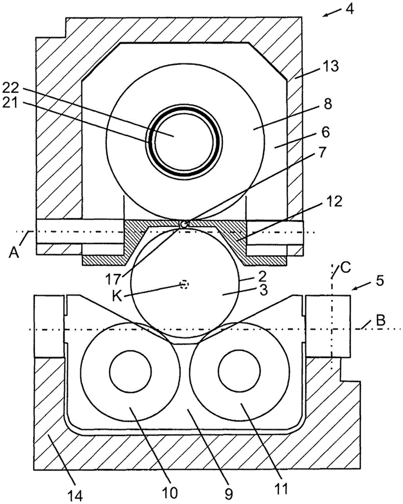
[0031] attached figure 1 The polishing head 4 and the backup roller head 5 on the crankshaft 3 are shown in a schematic cross-section perpendicular to the crankshaft axis K of the crankshaft 3 . The illustrated bearing surface 2 of the crankshaft 3 is the main bearing seat of the crankshaft 3 . The connecting rod bearing and the bearing seat of crankshaft 3 and the remaining bearings can also be processed by polishing head 4 . The polishing head 4 and the backup roller head 5 are narrowly shaped perpendicular to the plane shown, so that there is a distance from the two crank arms connected to the bearing surface 2 in each case. The backup roll head 5 supports the crankshaft 3 against the rolling force exerted on the crankshaft 3 by the polishing head 4 via the polishing roll 7 .

[0032] The polishing head 4 has a polishing head housing 6 which is rotatably mounted about a first rotational axis A in the rolling tool 1 according to the invention in a polishing head frame 13 ....


PUM


Abstract

The invention relates to a rolling tool (1) for the roller burnishing of bearing surfaces (2) of a crankshaft (3) that can be rotated about a crankshaft axis (K), comprising a roller burnishing head (4) and a supporting roller head (5). The problem addressed by the invention is that of designing such a rolling tool in such a way that damage to guides of the burnishing roller or of the crankshaft is largely impossible. This problem is solved in that the burnishing roller (7) is guided on all sides in a roller cage (12) and in that the roller burnishing head (4) has a roller burnishing head frame (13), in which the roller burnishing head housing (6) is supported pivotably about a first pivot axis, which is perpendicular to the crankshaft axis (K) and which extends parallel to a tangent to a working side of the burnishing roller (7). Additionally or alternatively thereto, the supporting roller head (5) comprises the supporting roller frame (14), in which the supporting roller housing (9) can be pivoted about a second pivot axis (B), which is perpendicular to the crankshaft axis (K) and parallel to the first pivot axis (A), and about a third pivot axis (C), which is perpendicular to the crankshaft axis (K) and perpendicular to the first pivot axis (A).

Description

technical field [0001] The invention relates to a rolling tool for polishing bearing surfaces of a crankshaft rotatable about the crankshaft axis, the rolling tool having a polishing head and a backup roller head, wherein the polishing head has a polishing roller and is mounted in a polishing head housing and The pressure roll supporting the polishing roll and wherein the backing roll head has two backing rolls mounted in a backing roll shell, by means of which the crankshaft can be supported against the rolling force acting on the crankshaft by the polishing roll. Background technique [0002] Internal combustion engines such as automobile engines have been developed towards smaller engines, smaller bearings and higher loads on the crankshaft. Highly loaded bearing parts operate under mixed friction conditions, in which the lubricating oil layer consisting of engine oil does not completely separate the crankshaft bearing surface and the counter-moving surface from each othe...

Claims


Application Information

Patent Timeline
Patent Type & Authority Applications(China)
IPC IPC(8): B24B39/04B24B41/02B24B41/00
CPCB24B39/04B24B41/002B24B41/02B21H7/185B23P9/02B23P2700/07B24B5/42
Inventor 阿尔弗雷德·海曼杰德瑞·麦丹尔
Owner HEGENSCHEIDT MFD
Why Eureka
Try Eureka