Method for operating a piezo servo injector

A technology of injectors and piezoelectric actuators, applied to fuel injection valves driven by fluid pressure, fuel injection devices, fuel injection control, etc., can solve the problems of accuracy and robustness, slow adaptation methods, etc., to achieve The effect of high accuracy and high level of robustness

Active Publication Date: 2016-06-29
VTESCO TECH GMBH
View PDF5 Cites 0 Cited by
  • Summary
  • Abstract
  • Description
  • Claims
  • Application Information

AI Technical Summary

Problems solved by technology

However, this known adaptation method is relatively slow, and

Method used


Image

  • Method for operating a piezo servo injector
  • Method for operating a piezo servo injector

Examples


Embodiment Construction

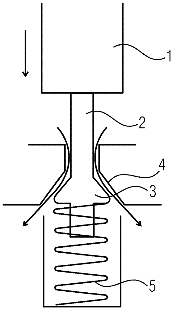
[0020] figure 1 A part of an injector of an internal combustion engine is shown, the nozzle needle (not shown) of which is actuated by a piezoelectric actuator 1 by means of a servo valve 2 . The servo valve 2 has a mushroom-shaped valve body 3 interacting with a valve seat 4 . The spring 5 presses the valve body 3 against the valve seat 4 . When voltage is applied to the piezoelectric actuator 1, said piezoelectric actuator expands downwards in the figure and in this way the valve body 3 of the servo valve 2 is downwards in the figure due to the force of the spring 5 The movement is such that a flow channel is thus opened between the valve seat 4 and the valve body 3 , through which the fuel flows and thus enables a movement of the nozzle needle (not shown) for starting the injection process to be carried out.

[0021] When the voltage applied to the piezoelectric actuator 1 is turned off, the piezoelectric actuator contracts, causing the valve body 3 to move the spring 5 u...


PUM


Abstract

The invention describes a method for operating an injector of an internal combustion engine, the nozzle needle of said injector being operated by a piezo actuator by means of a servo valve. The idle travel of the piezo actuator is eliminated by maintaining a permanent direct force connection between the piezo actuator and the servo valve, so that a change in force on the servo valve due to a change in pressure in the valve chamber when the servo valve is opened and closed and when the nozzle needle of the injector is closed is always transmitted to the piezo actuator as a change in force. The resulting change in voltage and/or capacitance of the piezo actuator is detected, and parameters with which the injection quantity output by the injector is regulated are determined from the result of the detection. A particularly high degree of quantity metering accuracy can be achieved in this way.

Description

technical field [0001] The invention relates to a method for operating an injector of an internal combustion engine, the nozzle needle of which is operated by a piezoelectric actuator via a servo valve. Background technique [0002] In this type of injector, the nozzle needle of the injector is not directly connected to the piezoelectric actuator whose expansion and contraction produces the opening and closing movement of the nozzle needle, while the servo valve is located in the nozzle needle Between the piezoelectric actuator, the valve body of the servo valve is connected to the piezoelectric actuator, and due to the expansion of the actuator, the servo valve is lifted away from the valve seat. This occurs against the force of the valve spring, which presses the valve body against the valve seat. Lifting the valve body of the servo valve away from the valve seat causes fuel flow, thereby causing operation of the associated nozzle needle. [0003] In this type of injecto...

Claims


Application Information

Patent Timeline
IPC IPC(8): F02M65/00F02M63/00F02D41/20F02D41/40F02M47/02
CPCF02D41/2096F02D41/401F02D2041/2051F02D2041/2055F02D2200/0616F02M47/027F02M63/0026F02M63/0043F02M63/0068F02M2547/006F02M2547/008Y02T10/40
Inventor 张宏
Owner VTESCO TECH GMBH
Why Eureka
Try Eureka