Slide ring seal arrangement with improved outflow behaviour for a cooling and/or barrier medium

A technology of mechanical seals and mechanical seals, applied in mechanical equipment, engine components, engine seals, etc., can solve problems such as fluid flow loss, achieve low-loss flow, and improve cooling effects

Active Publication Date: 2016-06-29
EAGLEBURGMANN GERMANY GMBH &CO KG
View PDF6 Cites 5 Cited by
  • Summary
  • Abstract
  • Description
  • Claims
  • Application Information

AI Technical Summary

Problems solved by technology

However, the fluid supplied to the mechanical seal must undergo several direction changes due to the rotation of the rotary slip ring and t...

Method used


Image

  • Slide ring seal arrangement with improved outflow behaviour for a cooling and/or barrier medium
  • Slide ring seal arrangement with improved outflow behaviour for a cooling and/or barrier medium
  • Slide ring seal arrangement with improved outflow behaviour for a cooling and/or barrier medium

Examples


Embodiment Construction

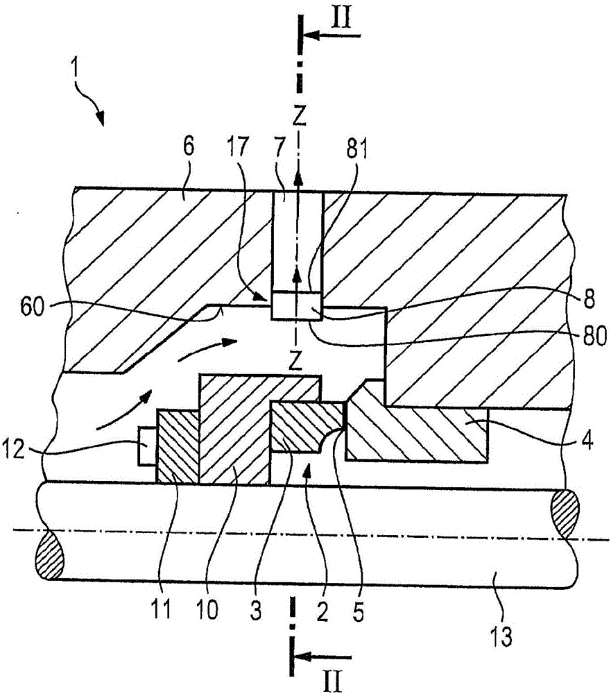
[0022] The following will refer to figure 1 and figure 2 The mechanical seal device 1 according to the first exemplary embodiment of the present invention is explained in detail.

[0023] Such as figure 1 As shown, the mechanical seal device 1 includes a mechanical seal 2 with a rotating slip ring 3 and a stationary slip ring 4 . The two slide rings define a sealing gap 5 between them.

[0024] The fixed slip ring 4 is fixed to the housing assembly 6 .

[0025] The rotary slip ring 3 is connected to a shaft 13 via an entrainment element 10 . The transmission element 10 thus transmits the torque from the shaft 13 to the rotary slip ring 3 .

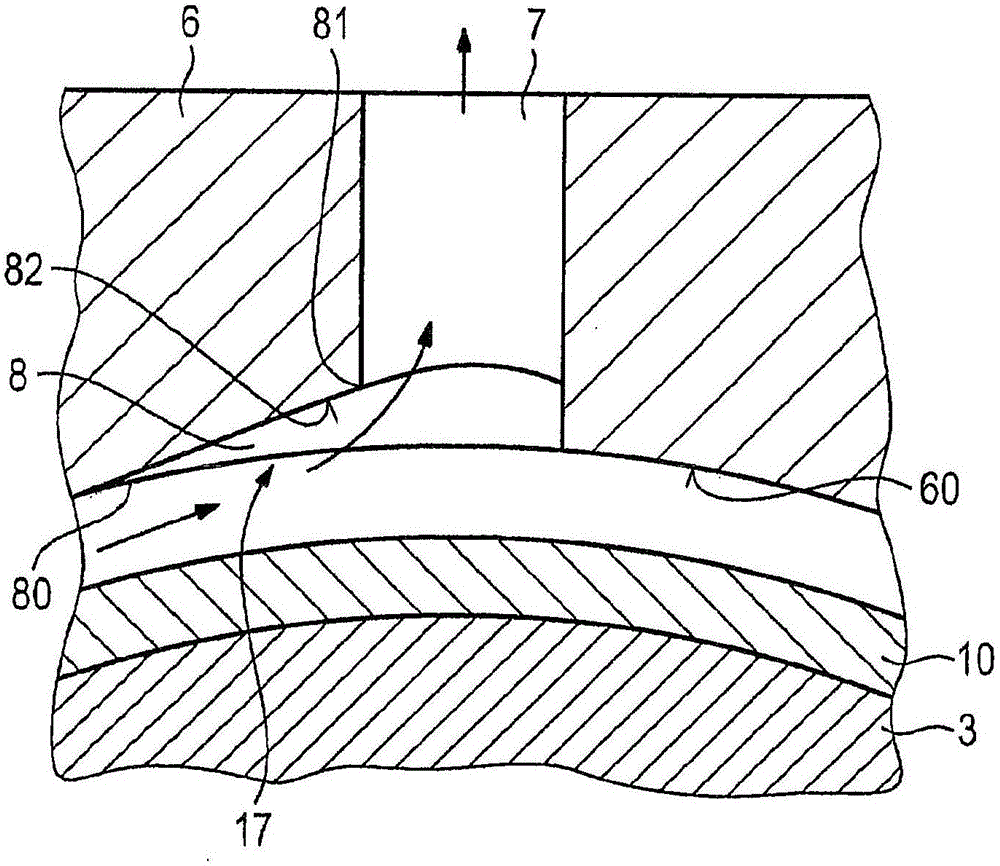
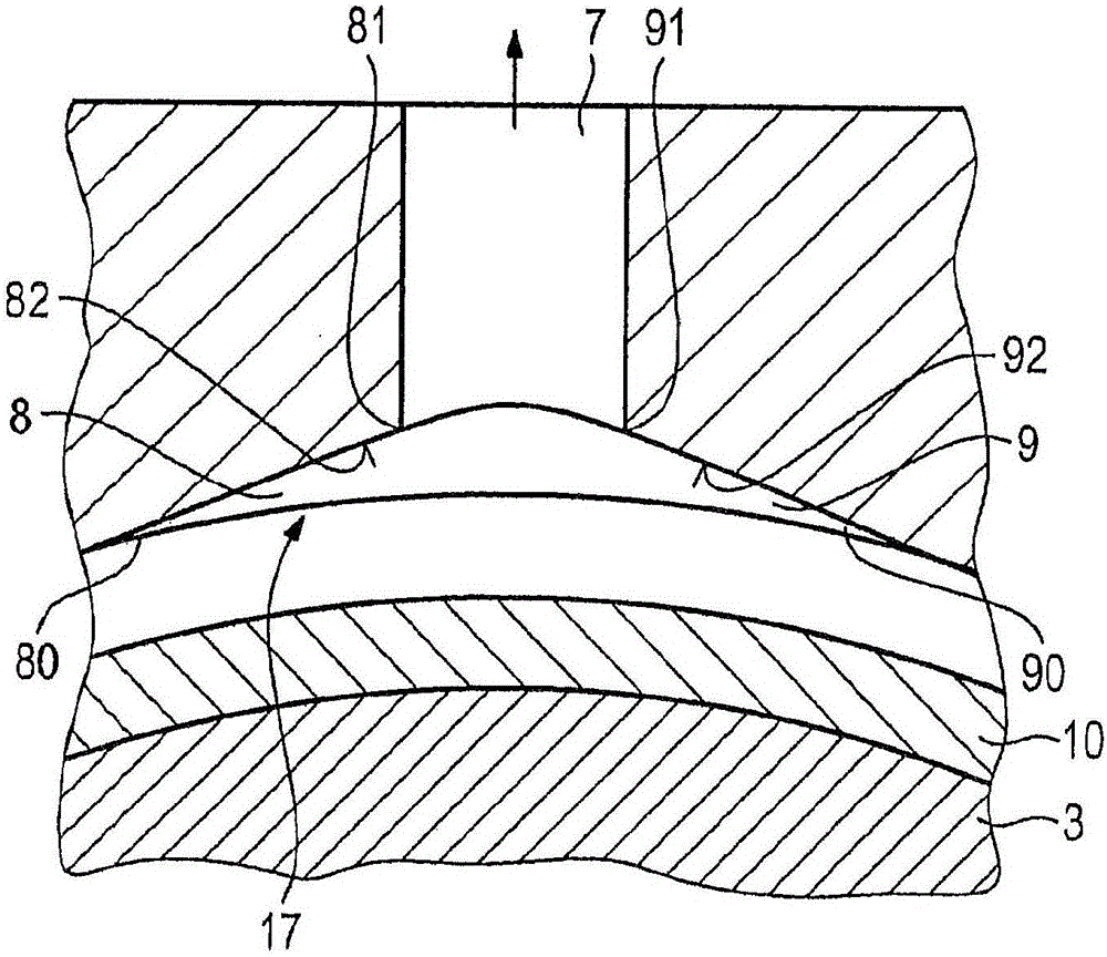
[0026] Furthermore, an internal conveying device 11 with blades 12 is arranged on a shaft 13 . The internal delivery device 11 rotates together with the shaft 13 and serves to deliver fluid to the mechanical seal 2 . The fluid can be, for example, a sealing medium or a coolant. exist figure 1 and figure 2 Fluid flow is indicate...


PUM


Abstract

The present invention relates to a slide ring seal arrangement, comprising: a slide ring seal (2) with a rotating slide ring (3) and a stationary slide ring (4) which define a sealing gap (5) between them, and a housing component (6) with an inner casing region (60), wherein the housing component (6) comprises an outlet opening (7) for removing a fluid guided to the slide rings, and an inflow region, wherein the inflow region has at least one transfer channel (8; 9) which extends in the circumferential direction and deepens continuously towards the outlet opening (7), which transfer channel is formed in the housing component (6) and opens at the outlet opening (7).

Description

technical field [0001] The present invention relates to a mechanical seal arrangement which improves the flow characteristics of a medium, more particularly a cooling and / or sealing medium, supplied to a slide ring of a mechanical seal. Background technique [0002] Various designs of mechanical sealing devices are known from the prior art. Typically, a cooling and / or sealing medium is supplied to the mechanical seal arrangement, which cooling and / or sealing medium is delivered by means of an internal delivery device. An example of such a mechanical seal is known from DE 10 2011 118 294.6, in which a Tesla pump is used as the internal delivery device. Other delivery devices include, for example, pump rings. A flow path extends from the internal delivery device to the slip ring where fluid is discharged via a discharge hole in the housing. In this case, the outlet opening is arranged radially relative to the slip ring. However, the fluid supplied to the mechanical seal mu...

Claims


Application Information

Patent Timeline
IPC IPC(8): F16J15/34
CPCF16J15/3404
Inventor J·菲希特纳S·莱迪希A·玛都斯赫克E·波奇曼J·斯科尔泽德罗
Owner EAGLEBURGMANN GERMANY GMBH &CO KG
Why Eureka
Try Eureka