
Static electric induction system

An electrostatic induction and guide technology, applied in transformer/inductor cooling, circuits, transformer/inductor components, etc., can solve problems such as affecting the insulation aging rate, affecting the life of the transformer, and the peak temperature area cannot be effectively cooled.

Active Publication Date: 2016-06-29
HITACHI ENERGY SWITZERLAND AG
View PDF8 Cites 2 Cited by
  • Summary
  • Abstract
  • Description
  • Claims
  • Application Information

AI Technical Summary

Problems solved by technology

Due to the symmetrical arrangement of the fluid control members, hot spots may spread easily, especially in the circumferential direction of the coil unit 16, and peak temperature regions cannot be effectively cooled
[0005] Due to the generation of losses in the windings, hot spots occur which affect the aging rate of the insulation and thus the lifetime of the transformer

Method used


Image

  • Static electric induction system
  • Static electric induction system
  • Static electric induction system

Examples


Embodiment Construction

[0069] The invention will now be described more fully hereinafter with reference to the accompanying drawings that illustrate certain embodiments of an electrostatic induction system. This invention may, however, be embodied in many different forms and should not be construed as limited to the embodiments set forth herein; rather, these embodiments of an electrostatic induction system or transformer system are provided by way of example so that this disclosure will be thorough and complete and fully convey the scope of the invention to those skilled in the art. Like numbers refer to like elements throughout the description.

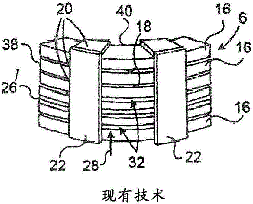
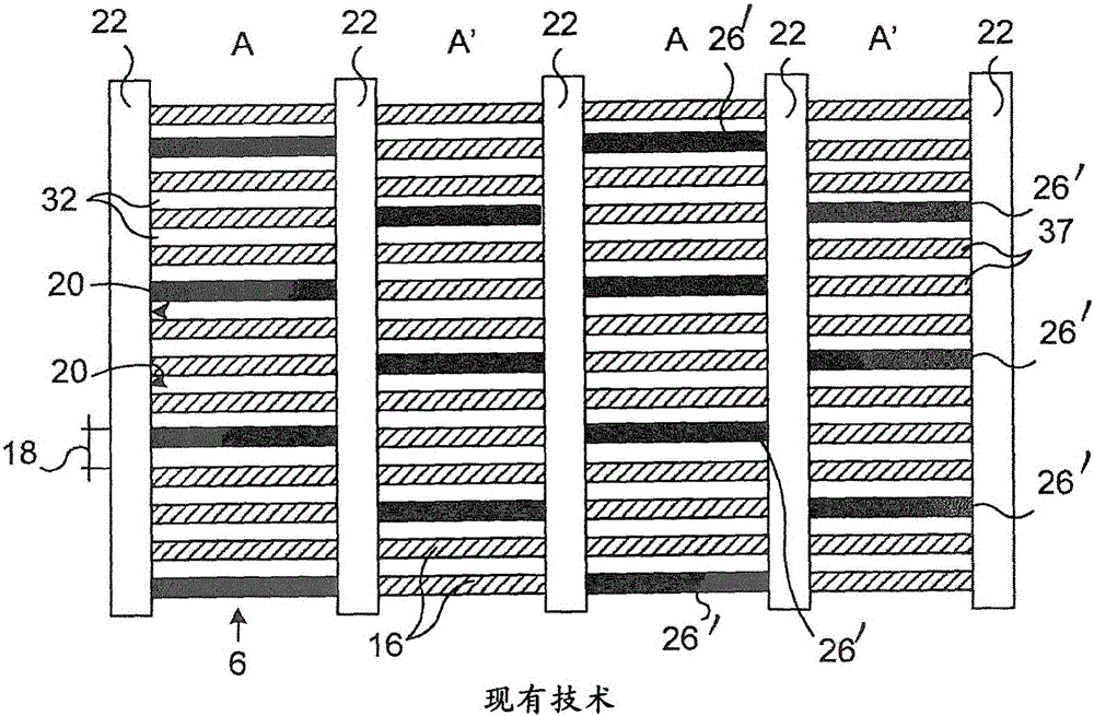
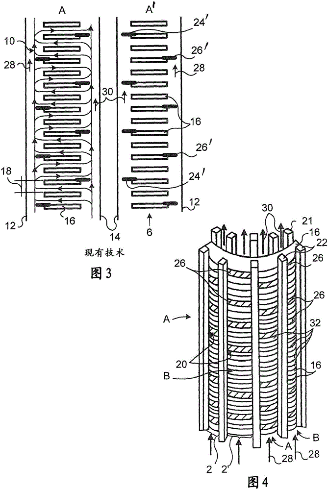
[0070] See illustration for prior art Figure 1 to Figure 3 , shows part of the coil assembly 6 of the electrostatic induction system 1 . The coil assembly 6 comprises several, in this case six, coil units 16 which are disk-shaped and arranged to be placed on top of each other spaced apart by coil unit spacers 20 . The coil unit spacer 20 may be arrang...


PUM


Abstract

The invention relates to a static electric induction system comprising cooling fluid, an outer shell (12) and an inner shell (14), a coil assembly (6) comprising a plurality of coil units (16), stacked on top of one another and positioned in between the outer and inner shells (12, 14), and a plurality of coil unit spacers (20) configured to form a plurality of intermediate fluid ducts (32) between the coil units (16). The static electric induction system further comprises a first and an adjacent second sector (2, 2), each sector(2, 2) comprising a fluid guide arrangement (A, B) having a plurality of fluid guides (24, 26), whereby the vertical distance, as counted in coil units (16), between one pair of two subsequent fluid guides (24, 26) of a sector (2, 2) differs from a vertical distance, as counted in coil units (16), between another pair of two subsequent fluid guides (24, 26) of the same sector (2, 2) and wherein the first fluid guide arrangement (A) of the first sector (2) differs from the second fluid guide arrangement (B) of the second sector (2).

Description

technical field [0001] The invention relates to electrostatic induction systems, such as transformer systems, which are normally cooled by a fluid. Background technique [0002] Known electrostatic induction systems such as core transformers consist of a tank containing a body made up of cores with several current carrying windings wound around them. Electrical windings or coils are arranged between the electrically insulating cylinders. The electrical windings may be embedded or shaped as disks arranged on top of each other. The electrical winding can also be helically shaped. When the transformer is in use the disc generates heat which needs to be dissipated by a cooling fluid such as eg oil or ester based liquid. Heat reduces the life expectancy of the transformer system and therefore generally requires the transformer system to be cooled by using an efficient and robust cooling system. The disks are usually vertically spaced apart by spacers to form horizontal fluid ...

Claims


Application Information

Patent Timeline
Patent Type & Authority Applications(China)
IPC IPC(8): H01F27/10H01F27/28H01F27/32
CPCH01F27/10H01F27/2876H01F27/322H01F27/323
Inventor T·拉内里德A·古斯塔弗森J·哈杰克J·克拉南博格R·贝尔弗德希拉
Owner HITACHI ENERGY SWITZERLAND AG
Features
  • Generate Ideas
  • Intellectual Property
  • Life Sciences
  • Materials
  • Tech Scout
  • Unparalleled Data Quality
  • Higher Quality Content
  • 60% Fewer Hallucinations
Learn More