
Plate flat bottom riveting connection process for flip-in rivets with bulges at centers

A rivet and flat-bottom technology, which is applied in the field of sheet metal flat-bottom punching riveting connection technology, can solve problems such as lower connection strength than punching riveting connection strength, large punch friction resistance, internal material damage, etc., to achieve reliable connection quality, small flow resistance, Effect of preventing damage and cracks

Active Publication Date: 2016-07-06
XI AN JIAOTONG UNIV
View PDF9 Cites 9 Cited by
  • Summary
  • Abstract
  • Description
  • Claims
  • Application Information

AI Technical Summary

Problems solved by technology

However, this traditional flat-bottom rivetless connection method has the following disadvantages: the material of the traditional flat-bottom rivetless connection flows upward from the bottom of the punch, and the friction resistance of the punch to it is large, which is easy to cause damage or even cracks to the internal material; The flow of the traditional flat-bottom riveted connection is a one-way reverse extrusion method, the resistance is large during flow, the external load required for forming is large, and the forming is difficult; the connection strength is lower than that of punch riveting connection

Method used


Image

  • Plate flat bottom riveting connection process for flip-in rivets with bulges at centers
  • Plate flat bottom riveting connection process for flip-in rivets with bulges at centers
  • Plate flat bottom riveting connection process for flip-in rivets with bulges at centers

Examples


Embodiment Construction

[0014] The present invention will be described in detail below in conjunction with the drawings.

[0015] The flat-bottom punching riveting connection process of a plate with a raised inverted rivet in the center includes the following steps:

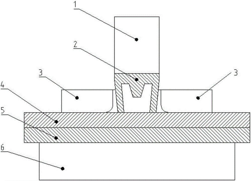
[0016] Reference figure 1 Before the flat-bottom punching and riveting connection starts, press the upper plate 4 and the lower plate 5 with the blank holder 3 on the lower die 6. The upper surface of the lower die 6 is flat and smooth. The center of the blank holder 3 is provided with a rivet 2, rivet 2. The upper end of is in contact with the punch 1, and the central axis of the punch 1 coincides with the central axis of the rivet 2.

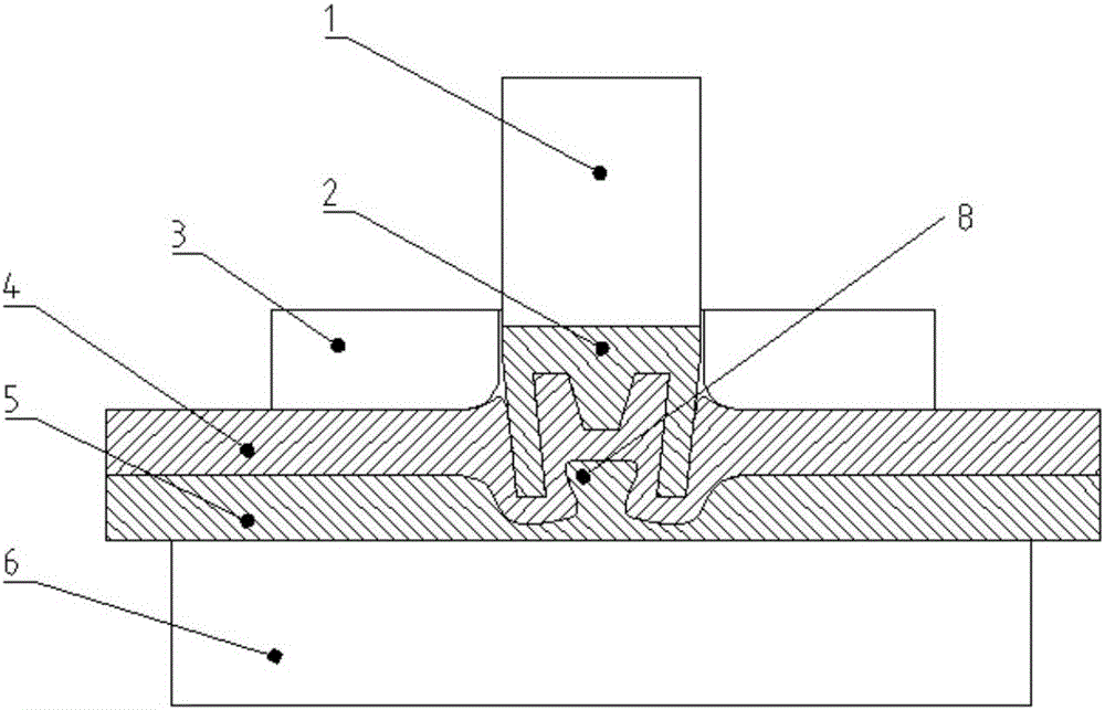
[0017] Reference figure 2 , After the flat-bottom punching and riveting connection starts, the punch 1 presses the rivet 2 into the upper plate 4 and deforms the upper plate 4 and the lower plate 5. The material of the plate cannot be Flow outwards. During the deformation of the upper plate 4 and the lower p...


PUM


Abstract

The invention discloses a plate flat bottom riveting connection process for flip-in rivets with bulges at the centers. Before the flat bottom riveting connection is started, an upper plate material and a lower plate material are pressed on a lower die by using a blank pressing ring, the upper surface of the lower die is flat and smooth, a rivet is arranged at the center of the blank pressing ring, a bulge is arranged at the center of the rivet, the bottom of the rivet is flip-in, and the upper end of the rivet contacts with a punch; after the flat bottom riveting connection is started, the rivet is pressed into the upper plate material by the punch so as to enable the upper and lower plate materials to deform, being pressed by the blank pressing ring, the materials of the plate materials cannot flow outwards, in the deformation process of the upper and lower plate materials, the materials of the plate materials flow toward the rivet, the material of the upper plate material is extruded into the rivet due to the flowing of the material of the lower plate material, so that the middle of the lower plate material is convex upwards to form an inner convex point which is embedded in the upper plate material to form a mechanical lock and then connect the upper and lower plate materials with each other, and the lower surface of the lower plate material is flat all the time. The process disclosed in the invention has the advantages of being reliable in connection quality and high in connection strength.

Description

Technical field [0001] The invention belongs to the technical field of plate connection, and particularly relates to a plate flat-bottom punching riveting connection process with a raised inverted rivet at the center. Background technique [0002] The traditional plate connection method has many problems when connecting aluminum alloy plates, but the rivet will penetrate the upper plate during the connection process, causing damage to the upper plate and inconvenience to sealing and anti-corrosion. In addition, there is a bump on the other side of the riveting connection point, which seriously affects the appearance. [0003] In recent years, some people have proposed the process of flat-bottom no riveting connection. However, this traditional flat-bottom non-rivet-free connection method has the following disadvantages: the traditional flat-bottom non-rivet-free connection material flows upward from under the punch, and the punch has a large frictional resistance to it, which is l...

Claims


Application Information

Patent Timeline
IPC IPC(8): B21J15/02B21J15/10
CPCB21J15/025B21J15/10
Inventor 赵升吨陈超韩晓兰崔敏超高家明吴凡
Owner XI AN JIAOTONG UNIV
Learn More