Shaft part polishing device suitable for different lengths and use method thereof

A technology for shaft parts and polishing devices, applied in the polishing field, can solve the problems of complex control procedures, complex workstation transfer steps, etc., and achieve the effects of reliable operation, convenient use, and accelerated polishing speed.

Pending Publication Date: 2016-07-06
NANAN DIQIAO CRAFTS CO LTD
5 Cites 0 Cited by

AI-Extracted Technical Summary

Problems solved by technology

Especially in the case of manual polishing, this polishing process that varies with different workpieces often involves more complicated and numerous polishing eq...

Method used

Owing to being provided with two groups of gears with different diameters and different modules that can drive the workpiece to rotate, it meshes with two groups of corresponding racks, so that the rotating speed of the workpiece and the pivoting moment that needs to be transmitted can be adjusted as required, Thereby completing two different polishing steps in one workstation. By arranging two sets of racks that can be engaged with each other one after the other, it can make the rack at the front end mesh with the corresponding gear set to complete the first polishing. The two sets of racks that are engaged with each other can also be polished The main movement and conveniently switch to parallel connection, that is, relative movement to each other, so that the second polishing can be realized. This enables...
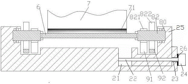
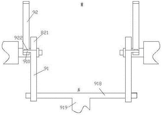
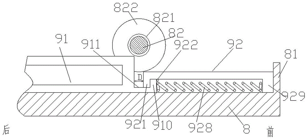

Abstract

The invention discloses a shaft part polishing device suitable for different lengths and a use method of the shaft part polishing device. The device comprises a polishing component with a polishing strip and a bearing base; a sliding groove is formed in the right end, a sliding seat is mounted in the sliding groove in a sliding manner, a driving screw is mounted in the sliding seat in a thread fit manner, the left end of the driving screw is rotatably mounted on the left side wall of the sliding groove, the right end of the driving screw penetrates an unthreaded hole formed in the right side wall of the sliding groove, and the driving screw is in power connection with an adjusting motor mounted at the outer end of the right side wall of the sliding groove; the left end of the bearing base and the sliding seat can be each rotatably provided with a clamping driving component in a bearing manner through a bearing; and a large gear located on the outer side and a small gear located on the inner side are fixedly mounted on the circumference face of each clamping driving component, the large gears are used for being engaged with outer side racks, and the small gears are used for being engaged with inner side racks, so that a shaft part is driven to press the polishing strip in an abutting manner and relatively rotate relative to the polishing strip so as to facilitate polishing operation, wherein the outer side racks and the inner side racks are arranged in a bilateral symmetry manner.

Application Domain

Polishing machinesGrinding drives +1

Technology Topic

EngineeringBilateral symmetry

Image

  • Shaft part polishing device suitable for different lengths and use method thereof
  • Shaft part polishing device suitable for different lengths and use method thereof
  • Shaft part polishing device suitable for different lengths and use method thereof

Examples

  • Experimental program(1)

Example Embodiment

[0010] Combine below Figure 1-3 The present invention will be described in detail.
[0011] A polishing device for a shaft part 6 according to an embodiment includes a polishing part 7 with a polishing bar 71 and a support base 8, and a sliding groove 21 is provided at the right end, and a sliding seat 25 is slidably installed in the sliding groove 21 A drive screw 22 is threadedly installed in the slide seat 25, the left end of the drive screw 22 is rotatably mounted on the left side wall of the slide groove 21, and the right end passes through the right side wall of the slide groove 21 The light hole 23 on the top is connected with the power adjustment motor 24 installed on the outer end of the right side wall of the sliding groove 21, and the left end of the support base 8 and the sliding seat 25 are rotatably supported by bearings 80 There is a clamping driving part 82, and the two clamping driving parts 82 are arranged oppositely so as to clamp the two ends of the shaft part 6 in place, and the circumferential surface of each of the clamping driving parts 82 is fixedly installed with The large gear 822 located on the outside and the pinion gear 821 located on the inside are used to respectively mesh with the symmetrically arranged outer rack 92 and inner rack 91 so as to drive the shaft parts 6 against the polishing bar 71 and face each other. When the polishing bar 71 is relatively rotated so as to carry out the polishing operation, the rear ends of the two inner racks 91 are provided with mounting holes, and the couplings for driving the two inner racks 91 are installed in the mounting holes. Rod 918, a driving handle 919 is fixedly arranged in the middle of the rear end of the connecting rod 918, and each front end of the two inner racks 91 is provided with a protruding horizontal bar 910 separated by a concave portion 911 opening upwards The rear end of each of the two outer racks 92 is provided with a protrusion 921 extending into the recess 911, and the lower side of the outer rack 92 is provided with a protrusion near the front side of the protrusion 921. The telescopic positioning tapered pin 922, when the protruding horizontal bar 910 is in a state of tight engagement with the protrusion 921, the telescopic positioning tapered pin 922 abuts against the front end surface of the protruding horizontal bar 910 Thus, the protruding horizontal bar 910 is fixed in place relative to the outer rack 92, at this time, there is a distance D between the rear side of the protrusion 921 and the rear side of the recess 911; The underside of the bar 92 is also provided with a pressing spring 928 that abuts against the front end protrusion 929 of the outer rack 92 so as to bias the protruding horizontal bar 910 backward; The front end of the front end is provided with a positioning convex wall 81 to engage with the front side of the outer rack 92 so as to limit its forward movement; Anti-vibration gasket 26, the anti-vibration gasket 26 is used to reduce the vibration generated when the adjustment motor 24 is running, so as to make the operation more stable.
[0012] Advantageously, wherein the driving handle 919 is a manually operated handle.
[0013] According to the embodiment, the use method of the polishing device, wherein, when the shaft part 6 needs to be re-polished, the polishing part 7 of the polishing bar 71 exerts a large loading force on the shaft part 6 , the driving handle 919 pushes the outer rack 92 forward to engage with the large gear 822 so as to re-polish the shaft part 6; when the shaft part 6 needs to be lightly polished , the polishing part 7 of the polishing bar 71 exerts a small loading force on the shaft part 6, and the driving handle 919 continues to push the outer rack 92 forward so that the front of the outer rack 92 The side engages the positioning convex wall 81 at the front end of the support base 8, thereby the outer rack 92 is limited; the driving handle 919 continues to move forward, so that the inner rack 91 overcomes the Press the biasing force of the spring 928 and press down the retractable positioning tapered pin 922 so as to move relative to the outer rack 92, so that the inner rack 91 drives the pinion 821 to rotate to drive The shaft part 6 is rotated to perform the light polishing.
[0014] Since there are two sets of gears with different diameters and different modules that can drive the workpiece to rotate, which mesh with two sets of corresponding racks, the rotation speed of the workpiece and the pivoting torque that needs to be transmitted can be adjusted according to the needs, so that in one The workstation performs two different polishing steps. By arranging two sets of racks that can be engaged with each other one after the other, it can make the rack at the front end mesh with the corresponding gear set to complete the first polishing. The two sets of racks that are engaged with each other can also be polished The main movement and conveniently switch to parallel connection, that is, relative movement to each other, so that the second polishing can be realized. This enables fast switching between two different polishing processes at the same workstation. In the case of heavy polishing, the large gear is used to mesh with the corresponding rack, so that a large torque can be transmitted; in the case of light polishing, the small gear is used to mesh with the corresponding rack, so that the polishing speed can be accelerated. And by setting the distance D between the two rack groups, it can be ensured that the interference effect of simultaneous meshing will not occur when the two groups of racks mesh with the corresponding gears; and the adjustment motor of the present invention can drive the sliding block to move left and right, thereby adjusting The distance between the two clamping drive parts can be applied to shaft parts of different lengths, and the versatility is stronger.
[0015] Through the above methods, those skilled in the art can make various changes according to the working modes within the scope of the present invention.

PUM

no PUM

Description & Claims & Application Information

We can also present the details of the Description, Claims and Application information to help users get a comprehensive understanding of the technical details of the patent, such as background art, summary of invention, brief description of drawings, description of embodiments, and other original content. On the other hand, users can also determine the specific scope of protection of the technology through the list of claims; as well as understand the changes in the life cycle of the technology with the presentation of the patent timeline. Login to view more.

Similar technology patents

Lacquer face polishing device

InactiveCN107053031AFast polishingreduce risk
Owner:张明来

Liquefied petroleum gas test copper strip polishing device

PendingCN107838796Ahigh degree of automationFast polishing
Owner:JIANGSU WHEATSTONE ELECTRIC AUTOMATION CO LTD

Method and equipment for polishing die

InactiveCN102975104AFast polishingReduce polishing labor intensity
Owner:BAODING TIANWEI GRP CO LTD

Control device for auxiliary current transformer and auxiliary current transformer system

InactiveCN102545550AVersatileUnified interface
Owner:ZHUZHOU CSR TIMES ELECTRIC CO LTD

Laser strapdown inertial navigation system

InactiveCN103353310Alow costVersatile
Owner:NORTHWESTERN POLYTECHNICAL UNIV

Classification and recommendation of technical efficacy words

  • Versatile
  • Fast polishing

Automobile electric control unit calibration system and method based on ASAP standard

InactiveCN101334662AVersatileResolve interface mismatch
Owner:CHONGQING UNIV OF POSTS & TELECOMM

Multi-bus automobile communication control module based on TCN

ActiveCN1889494AaccelerateVersatile
Owner:ZHUZHOU CSR TIMES ELECTRIC CO LTD

Variable capacity multi-cylinder rotary compressor and its running method

InactiveCN1955476Alow costVersatile
Owner:LG ELECTRONICS (TIANJIN) APPLIANCES CO LTD

Blood cell analyzer and analysis method

InactiveCN101407759AVersatileReagent saving
Owner:BEIJING INSTITUTE OF TECHNOLOGYGY

Method and equipment for polishing die

InactiveCN102975104AFast polishingReduce polishing labor intensity
Owner:BAODING TIANWEI GRP CO LTD

Lacquer face polishing device

InactiveCN107053031AFast polishingreduce risk
Owner:张明来

Liquefied petroleum gas test copper strip polishing device

PendingCN107838796Ahigh degree of automationFast polishing
Owner:JIANGSU WHEATSTONE ELECTRIC AUTOMATION CO LTD
Why Eureka
Try Eureka