Injection molding die

An injection molding and mold technology, which is applied in the field of switching injection molding processing molds, can solve the problems of low flexibility and efficiency of molding molds, affecting the fluidity and molding performance of raw materials, and limiting the heating performance of molds, so as to improve the flexibility of use and work. Efficiency, improved flow and surface molding quality, effect of improved flow and surface molding quality

Inactive Publication Date: 2016-07-06
PERLMAN ELECTRICAL KUSN
View PDF3 Cites 4 Cited by
  • Summary
  • Abstract
  • Description
  • Claims
  • Application Information

AI Technical Summary

Problems solved by technology

[0002] At present, the injection molding process of parts made of plastic and other materials is that the fluidity of the liquid raw material directly plays a decisive role in the molding efficiency and quality of the workpiece, because in order to improve the fluidity of the liquid raw material in the mold, it is often necessary to The mold heating mechanism is set in the molding mold to heat the mold. In actual use, the heating method of the injection molding mold is often to use high-temperature water or high-temperature oil to circulate inside the mold through pipelines to achieve the effect of heating the mold. Although this approach achieves the purpose of increasing the mold temperature and improving the fluidity of the raw material, because the heating temperature of water or oil as the medium is often relatively low, it severely limits the heating performance of the mold and affects the fluidity and molding performance of the raw material. At the same time, during the use of the mold, it needs to be transferred to the injection molding equipment through the mold base, so the flexibility and efficiency of the forming mold are relatively low. In view of this situation, it is urgent to develop an inventive Injection molding molds to meet the needs of actual production use

Method used


Image

  • Injection molding die
  • Injection molding die

Examples


Embodiment Construction

[0012] In order to make the technical means, creative features, goals and effects achieved by the present invention easy to understand, the present invention will be further described below in conjunction with specific embodiments.

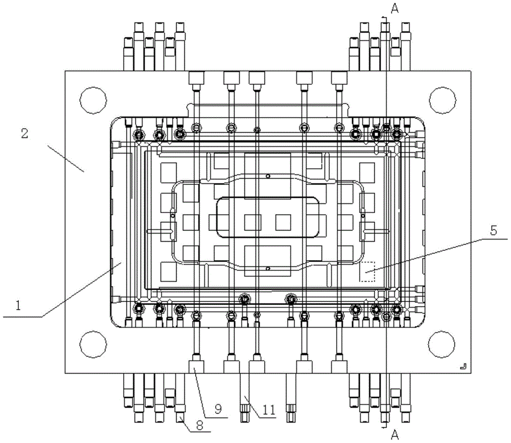
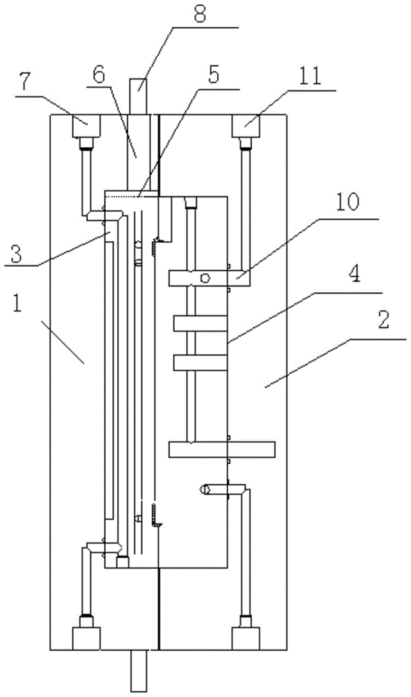
[0013] Such as figure 1 with figure 2 The above-described injection molding mold includes a front template 1, a front mold core 2, a rear template 3 and a rear mold core 4, wherein the front mold core 2 is embedded in the front template 1, and the rear mold core 4 is embedded in the rear template 3 , the front template 1 and the rear template 3 and the front mold core 2 and the rear mold core 4 are offset to form a closed molding cavity, and the front mold core 2 and the front template 1 and the rear mold core 4 and the rear template 3 are provided with heat insulation The groove 5 is isolated, and the steam heating circulation pipe 6 and the water temperature regulation circulation pipe 7 are arranged in the front template 1, and the steam heat...


PUM

PropertyMeasurementUnit
widthaaaaaaaaaa

Abstract

The invention relates to an injection molding die. The injection molding die comprises a front die plate, a front die core, a rear die plate and a rear die core. The front die core is embedded in the front die plate. The rear die core is embedded in the rear die plate. The front die plate abuts against the rear die plate and the front die core abuts against the rear die core, so that an airtight forming cavity is formed. A heat insulating groove is formed between the front die core and the front die plate so as to isolate the front die core from the front die plate, and a heat insulating groove is formed between the rear die core and the rear die plate so as to isolate the rear die core from the rear die plate. A steam heating circulating pipe and a water circuit temperature regulation circuiting pipe are arranged in the front die plate and both surround the front die core, and a steam port and a water circuiting port are formed in the lateral surface of the front die plate. A cooling water circuiting pipe is arranged in the rear die plate and surrounds the rear die core, and a cooling water receiving port is formed in the lateral surface of the rear die plate. According to the injection molding die, on one hand, the heating efficiency and quality of the injection molding die can be effectively improved; and on the other hand, the heating structure of the injection molding die can be effectively simplified, and the use flexibility and working efficiency of the injection molding die are improved.

Description

technical field [0001] The invention relates to an open and plastic mold, in particular to an injection molding mold. Background technique [0002] At present, the injection molding process of parts made of plastic and other materials is that the fluidity of the liquid raw material directly plays a decisive role in the molding efficiency and quality of the workpiece, because in order to improve the fluidity of the liquid raw material in the mold, it is often necessary to The mold heating mechanism is set in the molding mold to heat the mold. In actual use, the heating method of the injection molding mold is often to use high-temperature water or high-temperature oil to circulate inside the mold through pipelines to achieve the effect of heating the mold. Although this approach achieves the purpose of increasing the mold temperature and improving the fluidity of the raw material, because the heating temperature of water or oil as the medium is often relatively low, it severel...

Claims


Application Information

Patent Timeline
Patent Type & Authority Applications(China)
IPC IPC(8): B29C45/26B29C45/73
CPCB29C45/2602B29C45/7312
Inventor 齐鸣
Owner PERLMAN ELECTRICAL KUSN
Why Eureka
Try Eureka