Turnable lower berth for sleeper train and turning mode of the turnable lower berth
A lower berth and sleeper technology, which is applied to sleeper appliances, railway car body parts, seats, etc., can solve the problems that sleeper berths and seats cannot be flexibly converted, and achieve the best riding comfort, effective limit, and convenient operation
- Summary
- Abstract
- Description
- Claims
- Application Information
AI Technical Summary
Problems solved by technology
Method used
Image
Examples
Embodiment 1
[0026] According to the needs of passengers, the flight attendants will manually convert the lower berth into a sleeper state or a seat state. The specific method is as follows:
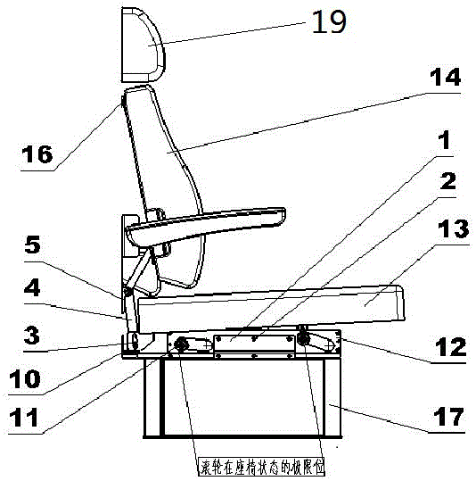
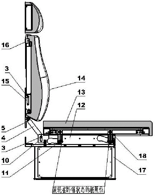
[0027] The sleeper state is converted into the seat state: the flight attendant presses down the edge of the berth with both hands and pushes it forward. The eight rollers located under the berth respectively move forward along the four track plates. When the berth moves forward, the connecting rod is driven clockwise. Swing, the connecting rod that swings clockwise drives the two backrest assemblies to swing counterclockwise around the four brackets fixed on the car body wall. When the eight rollers under the lower deck reach the limit position, the connecting rod assembly stops swinging clockwise At this time, the angle between the lower berth and the ground of the car body is 5 degrees, and the angle between the backrest and the wall of the car body is 5 degrees. Then the flight attendant turns the...
Embodiment 2
[0030]During the conversion process of the berth chair, the movement principle of the berth limit mechanism is as follows:
[0031] (1) Movement principle of the berth limit mechanism when the berth state is transformed into the seat state
[0032] The two groups of bearing housings 5 are fastened to the car wall respectively, the two groups of rollers 3 at the upper ends of the two groups of connecting rods 4 are respectively inserted into the chute of the backrest interface plate 15, and the two groups of rollers 3 at the lower ends of the two groups of connecting rods 4 are respectively inserted into the chute of the pavement interface board 10, when the crew presses down the pavement assembly 13 with both hands and pushes it forward, the eight rollers 11 located under the pavement assembly 13 move forward along the four track plates 12 on the chassis 17 respectively, When the pavement component 13 moves forward, it drives the two groups of connecting rods 4 to swing cloc...
PUM
 Abstract
Description
Claims
Application Information
 - R&D
- Intellectual Property
- Life Sciences
- Materials
- Tech Scout
- Unparalleled Data Quality
- Higher Quality Content
- 60% Fewer Hallucinations
Browse by: Latest US Patents, China's latest patents, Technical Efficacy Thesaurus, Application Domain, Technology Topic, Popular Technical Reports.
© 2025 PatSnap. All rights reserved.Legal|Privacy policy|Modern Slavery Act Transparency Statement|Sitemap|About US| Contact US: help@patsnap.com


