
A foldable lower berth for sleeper trains and its foldable method

A technology for lower bunks and sleepers, which is applied to sleeper appliances, railway car body parts, seats, etc., can solve the problem that sleepers and seats cannot be flexibly converted, and achieve the effect of optimal riding comfort, space saving and convenient operation.

Active Publication Date: 2018-12-07
SHANGHAI TANDA RAILWAY VEHICLE SEAT SYST CO LTD
View PDF4 Cites 1 Cited by
  • Summary
  • Abstract
  • Description
  • Claims
  • Application Information

AI Technical Summary

Problems solved by technology

[0005] The purpose of the present invention is to provide an improved foldable lower berth for sleeper trains and its fold-over method, which can overcome some deficiencies in the prior art that cannot be flexibly converted between sleeper berths and seats

Method used


Image

  • A foldable lower berth for sleeper trains and its foldable method
  • A foldable lower berth for sleeper trains and its foldable method

Examples


Embodiment 1

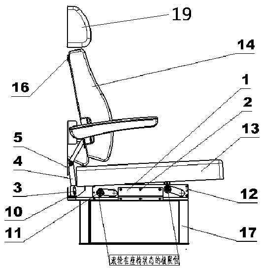
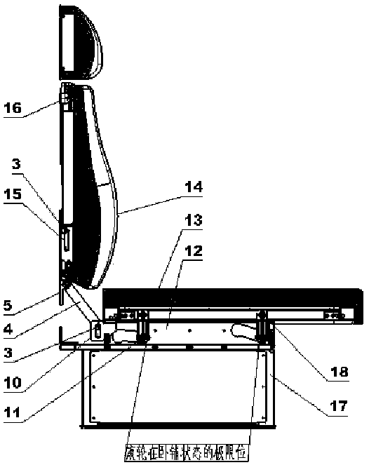
[0026] According to the needs of passengers, the flight attendants will manually convert the lower berth into a sleeper state or a seat state. The specific method is as follows:

[0027] The sleeper state is converted into the seat state: the flight attendant presses down the edge of the berth with both hands and pushes it forward. The eight rollers located under the berth respectively move forward along the four track plates. When the berth moves forward, the connecting rod is driven clockwise. Swing, the connecting rod that swings clockwise drives the two backrest assemblies to swing counterclockwise around the four brackets fixed on the car body wall. When the eight rollers under the lower deck reach the limit position, the connecting rod assembly stops swinging clockwise At this time, the angle between the lower berth and the ground of the car body is 5 degrees, and the angle between the backrest and the wall of the car body is 5 degrees. Then the flight attendant turns the...

Embodiment 2

[0030]During the conversion process of the berth chair, the movement principle of the berth limit mechanism is as follows:

[0031] (1) Movement principle of the berth limit mechanism when the berth state is transformed into the seat state

[0032] The two groups of bearing housings 5 ​​are fastened to the car wall respectively, the two groups of rollers 3 at the upper ends of the two groups of connecting rods 4 are respectively inserted into the chute of the backrest interface plate 15, and the two groups of rollers 3 at the lower ends of the two groups of connecting rods 4 are respectively inserted into the chute of the pavement interface board 10, when the crew presses down the pavement assembly 13 with both hands and pushes it forward, the eight rollers 11 located under the pavement assembly 13 move forward along the four track plates 12 on the chassis 17 respectively, When the pavement component 13 moves forward, it drives the two groups of connecting rods 4 to swing cloc...


PUM


Abstract

The invention relates to a turnable lower berth for a sleeper train. The turnable lower berth is characterized in that an upper berth surface is in rotational connection with a train body wall surface by a group of turning support arms; a positioning mechanism is arranged on the upper berth surface; the part below a lower berth surface is connected with the bottom side of the train body through a bottom rack; the lower berth surface is in sliding connection with the bottom rack through a sliding limiting mechanism; a connecting rod component is arranged on one side of a backrest component; a bracket is arranged on the train body wall surface; one end of the connecting rod component is connected with the bracket; the other end of the connecting rod component is connected with the sliding limiting mechanism. After a steward manually opens a locking hole, the positioning mechanism can unlock the upper berth surface and can be positioned and locked again after the upper berth surface is turned over or unfolded, and then turning operation of the upper berth surface can be completed; with the cooperation of the sliding limiting mechanism and the backrest component, the lower berth surface can be stretched and withdrawn. The conversion process of the whole upper and lower berths is simple, convenient and safe and easy to operate, meanwhile the space is saved, and the best sitting comfort effect is achieved.

Description

technical field [0001] The invention relates to the technical field of train seats, in particular to a foldable lower berth for sleeper trains and a foldable way thereof. Background technique [0002] At present, trains generally only have simple sleepers and seats, and the two cannot be adjusted. For long-distance trains, the sleepers set up make the whole compartment look crowded. At the same time, the sleepers on the third floor make people lie comfortably. Sitting is depressing, because there is no backrest, so it is very tiring to sit for a long time. At the same time, it is very inconvenient for the elderly and children to climb up and down the upper berths, and safety accidents are prone to occur. Both comfort and safety could be improved. [0003] And the seat structure in the train, then generally only can carry out the fine-tuning of forward and backward angle, can't let people lie down comfortably, therefore, in the existing train, there is an urgent need for a s...

Claims


Application Information

Patent Timeline
Patent Type & Authority Patents(China)
IPC IPC(8): B61D31/00B61D33/00
CPCB61D31/00B61D33/0078
Inventor 韩建国倪健吴鹏飞王俊丁宁新石磊
Owner SHANGHAI TANDA RAILWAY VEHICLE SEAT SYST CO LTD
Learn More