Auto diverter for change of direction

A direction conversion and automatic steering technology, applied in the direction of conveyors, rollers, conveyor objects, etc., can solve the problems of inability to change the direction of entry and exit quickly, the support plate is easy to bend, and the rollers are easy to slide up and down.

Inactive Publication Date: 2016-07-06
斗进精工株式会社 +1
View PDF5 Cites 7 Cited by
  • Summary
  • Abstract
  • Description
  • Claims
  • Application Information

AI Technical Summary

Problems solved by technology

[0006] However, according to the above configuration, the two ends of the stone plate are connected to the chain, so when it is necessary to transfer large-sized items, the length of the stone plate needs to be extended, but the stone plate may not be able to withstand the weight of the item and bend
[0007] Although it is possible to support the back of the slab with a special support member, the support member will hinder the transfer of the slab
[0008] In addition, a curved support plate is attached to the side of the cut portion where the roller is inserted, and the roller is combined with the support plate, so when supporting a heavy item, the support plate is easy to bend, and even if it is not bent, the Installed only on one side of the cutting section, the roller tends to slide up and down, so the article cannot be supported reliably
[0009] Also, in the case where items enter the angle converter or move out of the linear transfer conveyor through the linear transfer conveyor, the items cannot be connected smoothly because there is a gap between the angle converter and the linear transfer conveyor
[0010] Also, since the stoppers are fixed, all the stoppers need to be released when the direction of entry and exit is changed from curved to linear, so the direction of entry and exit cannot be changed quickly, resulting in inefficiency

Method used


Image

  • Auto diverter for change of direction
  • Auto diverter for change of direction
  • Auto diverter for change of direction

Examples


Embodiment Construction

[0036] Hereinafter, embodiments of the direction-changing automatic steering device according to the present invention will be described with reference to the drawings.

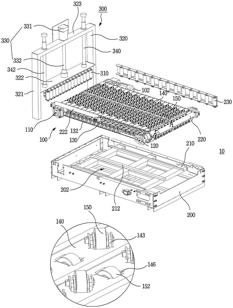
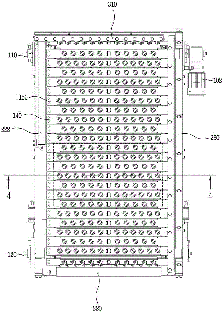
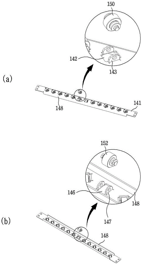
[0037] figure 1 In order to show the exploded perspective view of the direction conversion automatic steering device of the present invention, figure 2 for the floor plan, image 3 For the diagram showing the transfer plate, Figure 4 for figure 2 Sectional view along line 4-4 of the middle transfer plate.

[0038] In the following description, the direction in which the article enters the direction-switching automatic diverter 10 or moves out in a straight line is called the transfer direction, and the direction in which the article moves out of the direction-switching automatic diverter 10 at right angles is called the switching direction.

[0039] The direction changing automatic diverter 10 is composed of a chain transfer unit 100 and a housing 200 , and optionally has an entry and exit control unit...


PUM


Abstract

Disclosed is an automatic diverter to change direction comprising: a housing having a storage space inside and a support crossing in a longitudinal direction; a chain-type transfer unit straightly transferring an object in a first direction, stored and mounted on the storage space; and a moving control unit installed in one side of the chain-type transfer unit and moving the object from the chain-type transfer unit. The chain-type transfer unit comprises: an endless chain line performing track operation by a driving device; a transfer plate performing the track operation as the transfer plate is arranged along the chain line, and both ends are connected to the chain line; a direction changing roller supporting the object by being mounted on the transfer plate and coming in contact with the object, and rotating in a second direction which is at a fixated angle with the first direction; and a support roller mounted to protrude towards a lower surface of the transfer plate not to come in contact with the object, and coming in contact with the support to rotate in the first direction.

Description

technical field [0001] The invention relates to an automatic diverter for direction conversion, in particular to an automatic diverter for direction conversion capable of changing the transfer direction during the process of conveying articles by a conveyor. Background technique [0002] Usually, in the loading and unloading of articles or in the production line, in order to continuously transfer articles per unit process, it is necessary to use conveyor belts or conveyor rollers. At this time, due to the spatial characteristics of the work space or for the convenience of operation, it may be necessary to change the transfer direction of the article before transferring it. [0003] For this reason, Korean Patent No. 0846681 discloses a chain conveyor equipped with direction-changing rollers, which is characterized in that it includes: a chain conveyor, when driven by a driving means, the placed article W is moved along a straight line , and consists of a plurality of chain ...

Claims


Application Information

Patent Timeline
Patent Type & Authority Applications(China)
IPC IPC(8): B65G47/24B65G17/38
CPCB65G13/00B65G47/24B65G47/54B65G2811/0626B65G2811/0657
Inventor 朴喆奎
Owner 斗进精工株式会社
Why Eureka
Try Eureka