Concrete pump truck and vibration damping method for boom end of concrete pump truck

A technology for concrete pump trucks and concrete delivery pipes, which is applied in springs/shock absorbers, vibration suppression adjustment, and processing of building materials, etc. It can solve the problems of increasing the stress of the boom system, reducing the service life of the boom, and the difficulty of accurately controlling vibration, etc. problem, achieve the effect of reducing pumping shock, alleviating vibration, and reducing vibration

Active Publication Date: 2017-11-07
ZOOMLION HEAVY IND CO LTD
View PDF4 Cites 0 Cited by
  • Summary
  • Abstract
  • Description
  • Claims
  • Application Information

AI Technical Summary

Problems solved by technology

[0005] However, the above-mentioned anti-vibration measures have many shortcomings.
In the way of using the anti-vibration cylinder, the vibration caused by the discontinuous concrete impact on the boom of the pump truck during the construction process is unpredictable, and the vibration caused by the pulsating vibration generated by the anti-vibration oil cylinder to the end of the boom with different attitudes is also difficult. Accurate control, so it is difficult to obtain the ideal control effect by using two unpredictable quantities as the control basis, and the method of increasing the pulse vibration with opposite phase will inevitably increase the stress of the boom system and reduce the service life of the boom
In the method of controlling the piston of the boom cylinder through the vibration detection unit, the boom attitude and the vibration data of the boom end monitored by the monitoring unit in real time are used as control signals, the control algorithm is complex, the control parameters of different attitudes are ever-changing, and the control robustness is relatively low. Difference

Method used


Image

  • Concrete pump truck and vibration damping method for boom end of concrete pump truck
  • Concrete pump truck and vibration damping method for boom end of concrete pump truck
  • Concrete pump truck and vibration damping method for boom end of concrete pump truck

Examples


Embodiment Construction

[0034] The specific embodiments of the present invention will be described in detail below with reference to the accompanying drawings. It should be understood that the specific embodiments described herein are only used to illustrate and explain the present invention, and not to limit the present invention.

[0035] In the invention, unless otherwise stated, the orientation words used such as "up, down, top, bottom" usually refer to the direction shown in the drawings or refer to the vertical, vertical, or gravitational direction. The terms used to describe the mutual positional relationship of each part.

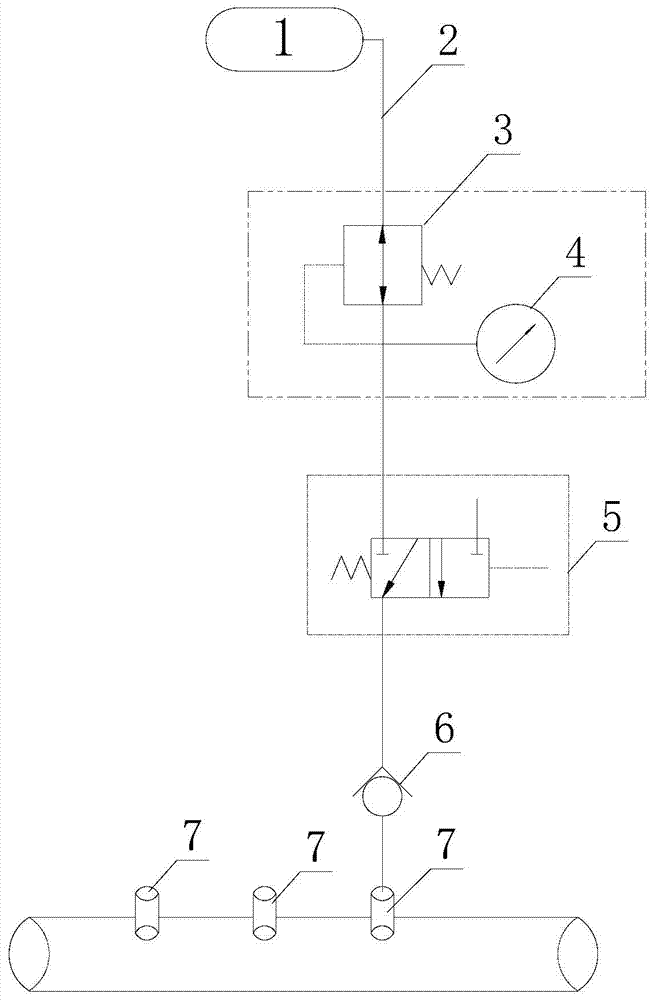
[0036] The present invention first provides a concrete pumping equipment, see figure 1 The pumping equipment includes a concrete conveying pipe and an inflatable system. The inflatable system includes a pressure gas source 1 and an inflatable pipe 2. The inflatable pipe 2 connects the pressure gas source 1 and the concrete conveying pipe to the cavity of the concrete conveying ...


PUM


Abstract

The invention discloses concrete pumping equipment and an arm rest tail end vibration reduction method for a concrete pump truck. The concrete pumping equipment comprises a concrete conveying pipe and a gas charging system. The gas charging system comprises a pressure gas source (1) and a gas charging pipeline (2), the gas charging pipeline is connected with the pressure gas source and the concrete conveying pipe so as to charge pressure gas into a pipe cavity of the concrete conveying pipe. The pressure gas is creatively charged into the concrete conveying pipe through the gas charging system which is additionally arranged, so that the continuous gas is charged into the discontinuous size of concrete which is pumped discontinuously, and pumped media flow continuously; thus, pumping impact is reduced radically, and the purpose of reducing the tail end vibration of an arm rest is achieved; in addition, the pressure gas is charged, so that multiphase flows are formed inside the concrete conveying pipe, internal energy consumption among the multiphase flows is increased, and vibration is also relieved radically. Therefore, in the construction process of the concrete pump truck, the arm rest tail end displacement vibration can be reduced initiatively, and the construction stability of the concrete pump truck is improved.

Description

Technical field [0001] The invention relates to the field of concrete pumping, in particular to a pumping equipment and a vibration reduction method thereof. Background technique [0002] Usually the concrete pump truck pumps concrete through the discontinuous intermittent action of double cylinders. Due to the discontinuity of concrete transportation, very large vibrations will be generated at the end of the boom end of the concrete delivery pipe (ie hose), resulting in the boom Fatigue, inaccurate end positioning, difficult pouring operation, and also increase the risk of operation. [0003] Various methods have been adopted in the prior art to relieve the vibration at the end of the boom caused by concrete transportation. For example, in the patent application with the publication number CN1932215A, a vibration suppression oil cylinder is used. Among them, the boom cylinder is connected with the vibration suppression cylinder, the pressure detection unit detects the pressure i...

Claims


Application Information

Patent Timeline
Patent Type & Authority Patents(China)
IPC IPC(8): E04G21/04F16F15/023
Inventor 万梁何利化世阳罗前星
Owner ZOOMLION HEAVY IND CO LTD
Why Eureka
Try Eureka