Wind turbine with liquid medium distribution system

a technology of liquid medium and wind turbine, which is applied in the direction of marine propulsion, vessel construction, greenhouse gas reduction, etc., can solve the problems of time-consuming and expensive manual distribution of liquid medium, and achieve the effect of convenient manufacture and convenient diversified design of the fourth distribution sub-system

Inactive Publication Date: 2012-01-10
SIEMENS AG
View PDF8 Cites 15 Cited by
  • Summary
  • Abstract
  • Description
  • Claims
  • Application Information

AI Technical Summary

Benefits of technology

[0015]The favourable arrangement of the liquid medium distribution system allows a transport of a liquid medium to desired locations which may be located anywhere in the wind turbine. The arrangement of the first, second and third distribution sub-systems, together with the tower-nacelle-interface and the nacelle-hub-interface, allow an effective distribution of the liquid media, meeting also requirements of a distribution via the two main rotating interfaces (tower-nacelle and nacelle-hub) in a wind turbine to the hub. Compared with prior art solutions, liquid media can be continually supplied to any part of the wind turbine, instead of only intermittently. The liquid medium is provided in a comfortable manner where, when and how it is needed. As a favourable consequence, periods of idleness of the wind turbine in order to perform regular maintenance works can be minimized. Maintenance tasks are simplified and speeded up. Therefore, by means of the liquid medium distribution system, a continuous flow of liquid medium is possible, which advantageously allows—despite a drastically reduced rate of maintenance with regard to common wind turbines—a continuous and substantially failure-free operation of the wind turbine according to the invention. In other words, a profitability of a wind turbine with the liquid distribution system according to the invention can advantageously be enhanced to a considerable extent.
[0019]The tower-nacelle-interface may be realized similar to the cooling fluid system in the U.S. Pat. No. 6,520,737. However, to allow a yawing of the nacelle relative to the tower, the electric connections from components in the nacelle to the tower is often realized via cables having a suitable length such that the nacelle may rotate, driven by motor or by the incoming wind, several times around the yawing axis. In an initial position of the nacelle the cables exhibit a sag and the cable twists further with each turn of the nacelle until the cable is too short to allow a further turn. Then, the nacelle is returned to the initial position using a motor driven by an appropriate controlling unit. In a cost-effective, and therefore preferred, embodiment of the invention the tower-nacelle-interface of the liquid medium distribution system of the wind turbine comprises a flexible hose with a sag, wherein an amount of the sag is dimensioned in accordance to a length of at least an electric cable running from the tower into the nacelle. In this way, the twisting and untwisting of the flexible hose can advantageously be synchronized with a twisting and untwisting of the electric cable.
[0021]In a further preferred embodiment, the first sub-interface comprises at least a first duct extending radially from an outer wall of the main shaft to the channel and a housing which encloses the main shaft annularly at an emersion position of the first duct at which the first duct intersects the outer wall of the main shaft. The housing is sealed against the main shaft and comprises a channel system through which the liquid medium from the pipe of the second distribution subsystem into the first duct during operation of the liquid distribution system. For example, the channel system in the housing may comprise an annular groove in the inner wall of the housing at the emersion position of the duct in the main shaft and a bore running radially from the grove to a junction at which a pipe of the second distribution sub-system may be connected. Alternatively or additionally the shaft may also comprise an annular groove on its outer side at the emersion position of the duct in the main shaft. Sealings between the housing and the main shaft may be on either side of the groove along an axial direction of the main shaft. Thus, an effective and safe transfer of the liquid medium from the pipe of the second distribution sub-system into the channel is enabled. Preferably, the housing of the first sub-interface is sealed to the rotating main shaft by means of a number of labyrinth seals. Using this reliable kind of conventional sealing, any loss or spilling of liquid medium at an intersection between the non-rotating housing and the rotating main shaft is minimized to an extent as much as possible. In a preferred embodiment, the main shaft is hollow alongside its longitudinal axis and the channel in the main shaft is a pipe or a tube. In this way, a comfortable guidance element in the form of a tube or a pipe for the liquid medium can be realized inside the main shaft and can easily be replaced or renewed. Also, by preventing a physical contact between the main shaft and the liquid medium, a possible harmful (e.g. chemical) contact between the liquid medium and a material of the main shaft can be avoided in this manner.
[0022]The first sub-interface advantageously comprises several first ducts as well as several channels. Accordingly, the housing may comprise also several bores and the housing and / or the main shaft may comprise several grooves at the emersion positions of the duct, each sealed against each other. In this way, different types of liquid media with different properties can be transported into the main shaft and onwards to the hub. Consequently, a further diversification of the liquid medium distribution system is facilitated. Also, an enhanced volumetric flow rate of the liquid medium through the main shaft is made possible in this manner.
[0024]Preferably, the second sub-interface comprises at least a second duct arranged in the hub, wherein the second duct is connected to the channel in the main shaft. A straightforward extension for the liquid medium from the channel in the main shaft into the hub is provided in this way. The second duct can be dimensioned separately in a quantitative and qualitative respect, for example as regards a number of second ducts or a physical diameter of the second duct, which should correspond to a physical diameter of the channel in the main shaft. A preferred essentially coaxial orientation of the second duct with respect to the channel in the main shaft allows an easy manufacture of the second duct, e.g. in a standardized milling process.
[0025]A further preferred embodiment of the wind turbine according to the invention is characterized in that a hub-blade-interface is provided in the hub, which hub-blade-interface connects the third distribution sub-system to a fourth distribution subsystem being located in at least one of the blades. In this manner, a further extension of the flow of the liquid medium is enabled into at least one of the blades, for example to provide a defrosting system in the blades with a defrosting liquid. Needless to say, depending on specific requirements, the fourth distribution sub-system can be arranged in alone or more of the blades of the wind turbine. The fourth distribution sub-system comprises a pipe and optionally at least one of the following items: a pump, a reservoir, a valve for accessing the liquid medium, an exit opening for the liquid medium. Thus, as already described for the first, the second and the third distribution sub-system, a useful diversified design of the fourth distribution sub-system is facilitated.

Problems solved by technology

Obviously, such a manual distribution of the liquid media is time-consuming and expensive.

Method used


Image

  • Wind turbine with liquid medium distribution system
  • Wind turbine with liquid medium distribution system
  • Wind turbine with liquid medium distribution system

Examples


Embodiment Construction

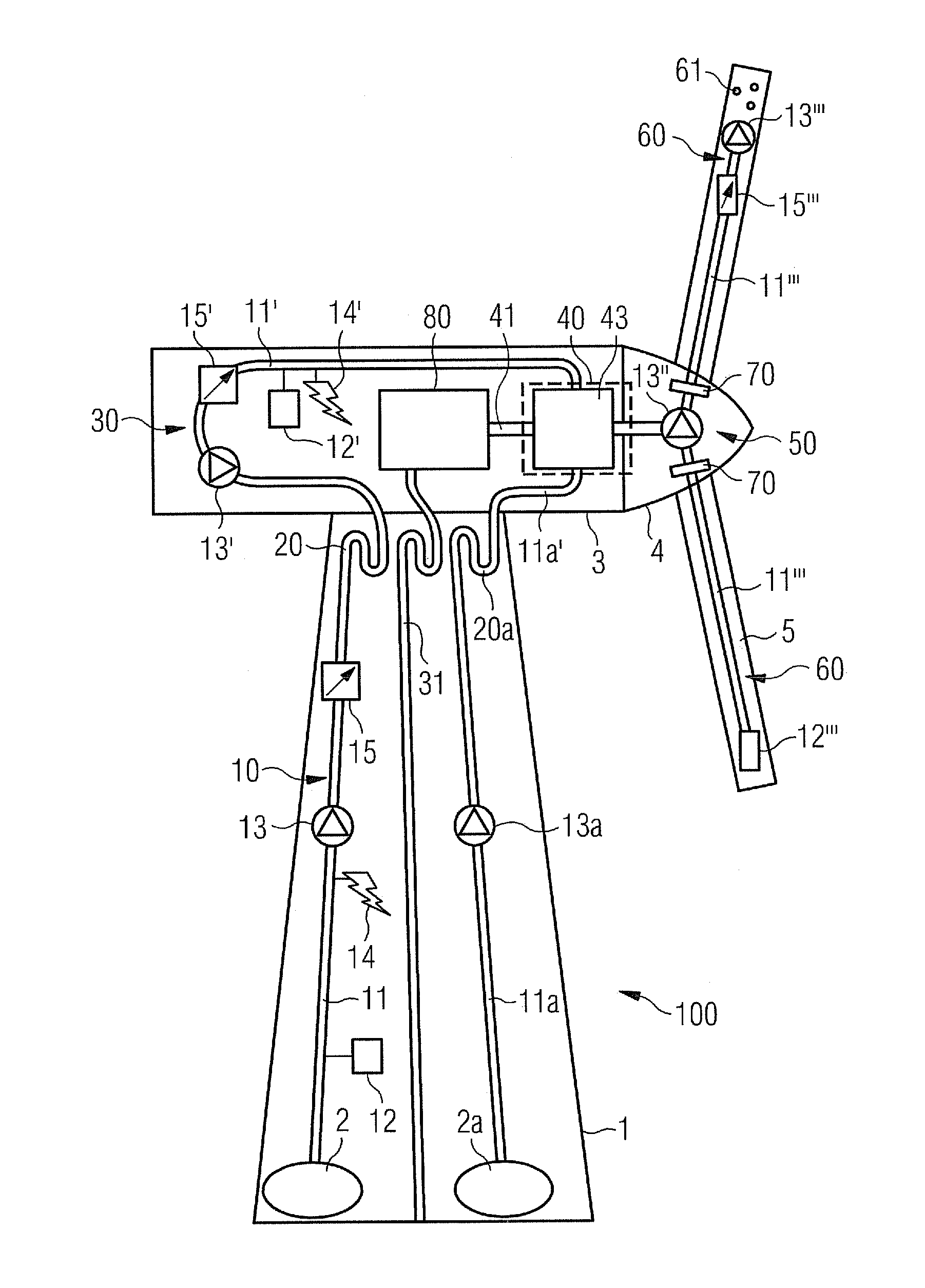
[0030]FIG. 1 shows an embodiment of a wind turbine according to the present invention. The wind turbine 100 comprises a tower 1, a nacelle 3 being rotatable supported by the tower 1, and a hub 4 being rotatable supported by the nacelle 3. Blades 5 are arranged on and fixed to the hub 4. The mentioned elements are conventional elements of a wind turbine 100 and will as such thus not be illustrated in more detail hereinafter. Furthermore, a normal operation of the wind turbine 100 is not in the focus of the invention and will thus also not be described in detail hereinafter. Only those items, elements and systems that are relevant to the invention will be elucidated in the following description.

[0031]Inside or outside (not shown) of the tower 1 is a source 2, 2a of liquid. Though explicitly two sources 2, 2a are shown in FIG. 1, it is possible that only one or more than two sources 2, 2a are arranged in the context of the invention. The term “source” is used generically in the context...


PUM


Abstract

A wind turbine with a tower, a nacelle, a main shaft, a hub and blades is provided. The wind turbine also includes a liquid medium distribution system for transport of liquid medium in the wind turbine. The liquid medium distribution system has a first distribution sub-system located in the tower, a second distribution sub-system located in the nacelle, a third distribution sub-system located in the hub, a tower-nacelle-interface connecting the first distribution sub-system to the second distribution sub-system, and a nacelle-hub-interface connecting the second distribution sub-system to the third distribution sub-system. Further, a method of transporting liquid medium in a wind turbine is provided.

Description

CROSS REFERENCE TO RELATED APPLICATIONS[0001]This application claims priority of European Patent Office Application No. 10155655.3 EP filed Mar. 5, 2010, which is incorporated by reference herein in its entirety.FIELD OF INVENTION[0002]The invention describes a wind turbine comprising a tower, a nacelle, a main shaft, a hub with blades, and a liquid medium distribution system for transport of liquid medium in the wind turbine. The invention further describes a method of transporting liquid medium in a wind turbine and a use of a liquid medium distribution system in a wind turbine.BACKGROUND OF INVENTION[0003]Liquid media may be transported in a wind turbine for a number of reasons. For example, a liquid medium may be part of a heating-system for the wind turbine or for other parts of the wind turbine.[0004]U.S. Pat. No. 7,168,251 discloses a wind energy turbine with a unit to be cooled by a cooling medium (gas or liquid) flowing in a cooling circuit from said unit to a heat exchange...

Claims


Application Information

Patent Timeline
Patent Type & Authority Patents(United States)
IPC IPC(8): F03D11/00
CPCF03D9/025F03D11/00F05B2260/205F05B2260/98Y02E10/721Y02E10/726Y02E60/17Y02E10/722F03D9/14F03D80/40F03D80/60F03D80/70Y02E10/72Y02E60/16Y02E70/30
Inventor BECKER, CHRISTIAN
Owner SIEMENS AG
Why Eureka
Try Eureka