Solar thermal collector system and sounding stave thereof
A technology of solar heat collectors and staves, applied in the field of solar energy, can solve problems such as the limitation of note position and display mode, insufficient absorption of solar heat, and poor practicability, so as to avoid heat collection blind spots, simple structure, and improve heat absorption efficiency effect
Inactive Publication Date: 2016-07-06
SHANDONG UNIV
5 Cites 3 Cited by
AI-Extracted Technical Summary
Problems solved by technology
However, the current solar collectors are all circular tube structures, which in some cases will lead to insufficient absorption of solar heat
[0003] In addition, reading and notation of staves is a difficult point in music education. Al...
Method used
All stave symbols are marked on the music staff panel 18, neatly arranged, moderate in size, so as to facilitate teaching.
As preferably, extend to both sides along the connecting position (i.e. the middle part of the tube sheet structure) of two tube sheet structures (i.e. the heat collecting tube A of Fig. 2 extends to B, C direction), the protrusion of the lower wall surface of the heat collecting tube 4 The density is getting higher and higher. The main reason is that the central part receives the least heat, and extending from the central part to both sides, the heat absorbed gradually increases. By continuously increasing the density of the protrusions, the water in the entire heat collecting tube 4 can be heated evenly, and the temperature in the middle can be avoided from being too low while the temperature on both sides is too high. This can also prevent the material of the heat collecting tube 4 in the middle from being easily damaged at high temperature for a long time, and can keep the temperature of the whole heat collecting tube even and prolong the service life.
Prior art generally all adopts circular tube structure, but finds to adopt circular tube structure in practice, when distance is relatively close between two circular tubes, because the distance between two close circular arcs is very small, makes The adjacent parts of the two circular tubes cannot fully absorb solar energy. As shown in Figure 10, if it is irradiated or reflected from the lower or upper part, the shadow part may not be illuminated, resulting in uneven local heat absorption of the heat collecting tube, which is easy to cause Damage to the collector tube. However, the present invention overcomes the shortcoming of the circular tube structure by arranging the cross-section of the heat collecting tube as a square tube structure, so that there is more space between adjacent heat collecting tubes 4 than the circular tubes, and the radiation from the upper part and the reflection from the lower part, The solar energy can be reflected in, so as to achieve uniform heat absorption, and reflect from other angles. Compared with the circular tube, it can also achieve the purpose of absorbing more heat.
[0045] As a preference, the focus D of the reflector 3 is located at the midpoint of the line connecting the lowest ends of the two tube-sheet structures. Through the above setting, it can ensure the absorption of solar energy to the greatest extent, avoiding the loss of solar energy due to...
Abstract
The invention provides a solar thermal collector system and a music stave system. The solar thermal collector system comprises heat collecting tubes, a reflecting mirror and heat collecting plates, wherein the adjacent two heat collecting tubes are connected through a corresponding heat collecting plate, so that the plurality of the heat collecting tubes and the adjacent heat collecting plates form a tubular plate structure; the cross sections of the heat collecting tubes are square; a temperature difference power generating device is connected to a powered device; and the powered device is a music stave. The invention provides a novel heat collector and a music stave system, which can improve the heat absorption capacity of solar energy, and can save energy resources.
Application Domain
Solar heating energySolar heat devices +6
Technology Topic
Absorption capacitySolar thermal collector +4
Image
Examples
- Experimental program(1)
Example Embodiment
[0038] The specific embodiments of the present invention will be described in detail below with reference to the accompanying drawings.
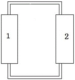
[0039] figure 1 A solar heat collector system is shown, the system includes a heat collector 1 and a heat utilization device 2 thereof, and the heat collector 1 and the heat utilization device 2 are connected by pipelines.
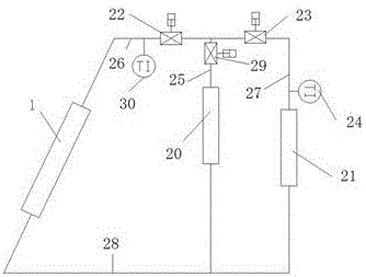
[0040] The collector structure is as figure 2 As shown, it includes heat collecting tubes 4, reflecting mirrors 3 and heat collecting plates 5, and two adjacent heat collecting tubes 4 are connected by heat collecting plates 5, so that a plurality of heat collecting tubes 4 and adjacent heat collecting plates 5 are connected to each other. A tube sheet structure is formed between the two tubes; the solar collector system includes two tube sheet structures, and a certain angle is formed between the two tube sheet structures, and the direction of the included angle is curved with the arc structure of the reflector. The directions are opposite, and the focal point D of the mirror 3 is located between the angles formed by the tube sheet structure.
[0041] As an improvement, the cross section of the heat collecting pipe 4 is a rectangle, and the heat collecting plate 5 is connected to the corners of the rectangle.
[0042] The prior art generally adopts the circular tube structure, but in practice, it is found that the circular tube structure is adopted, and when the distance between the two circular tubes is relatively close, because the distance between the two close arcs is very small, the two circular The adjacent parts of the tube cannot fully absorb solar energy, such as Figure 10 As mentioned above, if it is irradiated or reflected from the lower part or the upper part, the shadow part may not be illuminated, which will cause uneven heat absorption locally of the heat collecting tube, which is easy to cause damage to the heat collecting tube. However, the present invention overcomes the shortcoming of the round tube structure by setting the cross section of the heat collecting tube to be a square tube structure, so that there is more space between the adjacent heat collecting tubes 4 compared with the round tube, and the irradiation from the upper part and the reflection from the lower part, So that the solar energy can be reflected in, so as to achieve uniform heat absorption, reflect from other angles, and also achieve the purpose of absorbing more heat compared to the round tube.
[0043] Preferably, the cross section of the heat collecting tube 4 is square.
[0044] The traditional heat collectors set the heat collecting tube directly at the focal point. Once the position is shifted, the heat will not be collected into the heat collecting tube. Reflected to the tube sheet structure, the heat is collected into the collector tubes 4 in the tube sheet structure. With this structure, even if the position of the tube sheet structure is changed due to installation or operation problems, the solar energy will still be collected into the heat collector tubes 4, thereby avoiding heat loss; at the same time, because the traditional heat collectors are directly arranged with the heat collector tubes In the focus, the local overheating of the heat collector tube is caused, the local loss of the heat collector tube is too large, the service life is too short, and even the inside of the heat collector tube is overheated, superheated steam is generated, and the entire heat collector tube is filled, resulting in excessive internal pressure of the heat collector tube and damage to the heat collector tube. The structure of the present application can not only fully absorb heat, but also relatively disperse the heat, avoid excessive heat concentration, make the overall heat collection tube absorb heat evenly, and prolong the service life of the heat collection tube.
[0045] As a preference, the focal point D of the mirror 3 is located at the midpoint of the line connecting the lowest ends of the two tube sheet structures. Through the above arrangement, the solar energy can be absorbed to the maximum extent, and the loss of the solar energy due to the shift of the focus can be avoided, and at the same time, it can also be ensured that the plate-like structure can minimize the blocked sunlight on the reflector 3 as much as possible. It is proved by experiments that the above structure has the best effect of solar energy absorption.
[0046] Preferably, the cross-sectional areas of the heat collecting tubes are different. Along the middle of the tube sheet structure (ie the highest position) to the lowest position on both sides (ie figure 2 In the extension direction of the heat collector tube A to the B and C directions), the cross-sectional area of the heat collector tube becomes larger and larger. In the experiment, it was found that extending from the middle to both sides, the heat absorption gradually increased. The main reason through analysis was that the heat was the least in the middle because of the blockage of the tube sheet structure, while the heat absorption gradually increased when extending from the middle to both sides. By increasing the cross-sectional area of the collector tube, the water flow in the lower part can be increased, the water in the entire collector tube can be heated evenly, and the temperature on both sides is too high and the temperature in the middle is too low. In this way, the material of the middle heat collecting tube can be prevented from being easily damaged under high temperature for a long time, the temperature of the whole heat collecting tube can be kept uniform, and the service life can be prolonged.
[0047] Preferably, along the middle of the tube sheet structure (ie the highest position) to the lowest positions on both sides (ie the highest position) figure 2The increase in the cross-sectional area of the heat collector tube gradually becomes smaller in the extension direction of the heat collector tube A to the B and C directions. It was found in experiments that for heat absorption, along the middle of the tube sheet structure (ie the highest position) to the lowest positions on both sides (ie the highest position) figure 2 The increase in the extension direction of the heat collector tube A to B and C) gradually decreases, so the tube diameter is changed in this way to meet the corresponding requirements.
[0048] Preferably, the ratio of the largest cross-sectional area to the smallest cross-sectional area is less than 1.22.
[0049] Preferably, protrusions for enhancing heat transfer are provided on the lower wall surface of the tube sheet structure (the surface opposite to the reflector 3 ), so as to enhance the absorption of solar energy. Along the middle of the tube sheet structure (ie the highest position) to the lowest position on both sides (ie figure 2 In the extending direction of the heat collecting tube A (direction B and C), the height of the protrusion of the lower wall surface of the heat collecting tube 4 is getting higher and higher. In the experiment, it was found that extending from the middle to both sides, the heat absorption gradually increased. The main reason through analysis was that the heat was the least in the middle because of the blockage of the tube sheet structure, while the heat absorption gradually increased when extending from the middle to both sides. By increasing the height of the bulge continuously, the water in the entire heat collecting tube 4 can be heated evenly, avoiding that the temperature on both sides is too high and the temperature in the middle is too low. In this way, the material of the middle heat collecting tube can be prevented from being easily damaged under high temperature for a long time, the temperature of the whole heat collecting tube can be kept uniform, and the service life can be prolonged.
[0050] Preferably, along the connection position of the two tube sheet structures (that is, the middle of the tube sheet structure) to both sides (that is, the middle of the tube sheet structure) figure 2 The heat collecting tube A extends in the directions B and C), and the bulge density on the lower wall surface of the heat collecting tube 4 is getting higher and higher. The main reason is that the middle part receives the least heat, while extending from the middle part to both sides, the absorbed heat gradually increases. Through the continuous increase of the bulge density, the heating of the water in the entire heat collecting tube 4 can be made uniform, and the temperature in the middle is too low and the temperature on both sides is too high. In this way, the material of the middle heat collecting tube 4 can be prevented from being easily damaged under high temperature for a long time, the temperature of the whole heat collecting tube can be kept uniform, and the service life can be prolonged.
[0051] Preferably, the outer wall of the heat collector tube 4 can be provided with external fins, for example, straight fins or spiral fins can be set. the middle) to both sides (i.e. figure 2 The collector tube A extends in the directions B and C), and the height of the outer fins gradually decreases. The main reason is the same reason that the bump was set up earlier.
[0052] Preferably, inner fins 6 are arranged inside the heat collecting tube, and the inner fins 6 are connected to the diagonal corners of the rectangle, such as image 3 shown. The inner fins 6 divide the inside of the heat collecting tube 4 into a plurality of small channels 8, and the inner fins are provided with communication holes 7, so that the adjacent small channels 8 communicate with each other.
[0053] By arranging the inner fins 6, the inside of the heat collecting tube 4 is divided into a plurality of small channels 8, which further enhances the heat transfer, but the pressure of the corresponding fluid flow increases. By setting the communication holes 7, the communication between the adjacent small channels 8 is ensured, so that the fluid in the small channel with high pressure can flow into the adjacent small channel with low pressure, and the pressure of each small flow channel 8 inside the condensation end can be solved. The problems of unevenness and excessive local pressure promote the full flow of the fluid in the heat exchange channel. At the same time, through the arrangement of the communication hole 27, the pressure inside the heat collector tube is also reduced, the heat exchange efficiency is improved, and the The service life of the collector tube.
[0054] Preferably, along the flow direction of the fluid in the heat collecting tube 4, the area of the communication hole 7 increases continuously.
[0055] The communication hole 7 is a circular structure, and the radius of the circular structure increases continuously along the flow direction of the fluid in the heat collecting tube 4 .
[0056] Because along the flow direction of the fluid in the heat collecting tube 4, the fluid in the heat collecting tube 4 continuously absorbs heat and even evaporates, so the pressure of the heat collecting tube increases continuously, and because of the existence of the communication hole 7, the pressure inside the heat collecting tube 4 increases. The distribution is becoming more and more uniform, so the area of the communication hole needs to be large. By setting it continuously larger, the heat exchange area can be increased through the change of the communication hole area under the condition of ensuring the uniformity and pressure inside the heat pipe, thereby improving the heat transfer efficiency.
[0057] Preferably, along the flow direction of the fluid in the heat collecting tube 4, the area of the communication hole 7 is continuously increased and the range is continuously increased. By setting in this way, it also conforms to the change rule of the flow pressure, further reduces the flow resistance, and at the same time improves the heat exchange efficiency. Through this setting, it is found through experiments that the heat exchange efficiency can be improved by about 9%, while the resistance remains basically unchanged.
[0058] Preferably, along the flow direction of the fluid in the heat collecting tube 4, the number of the communication holes 7 is distributed more and more, and further preferably, the continuous increase of the number of the communication holes 26 is continuously increased.
[0059] The distribution principle of the above-mentioned number is the same as the area reduction principle, and the flow area is reduced by the number distribution compared with the exact same number of communication holes.
[0060] In the actual experiment, it was found that the area of the communicating hole 7 should not be too small. If it is too small, the flow resistance will increase, which will lead to the weakening of heat exchange. The area of the communicating hole 7 should not be too large. decrease, thereby reducing the heat transfer effect. Similarly, the cross-sectional area of the heat collector tube 4 should not be too large, which will lead to too few heat exchange tubes distributed per unit length of the tube sheet structure, which will also lead to poor heat exchange effect, and the flow area of the heat collector tube should not be too small. This leads to an increase in flow resistance, resulting in poor heat transfer. Therefore, the distance between the communication hole 7 and the cross-sectional area of the heat collector tube and the distance between the adjacent communication holes 7 must meet certain requirements.
[0061] Therefore, the present invention is based on thousands of numerical simulations and test data of multiple heat collectors of different sizes, under the condition of meeting the industrial requirements under pressure (below 10MPa), and in the case of realizing the maximum heat exchange, summed up. Optimal collector size optimization relationship.
[0062] In the present invention, the size optimization is carried out under the condition that the cross section of the heat collecting tube 4 is square.
[0063] The length of the inner side of the square (that is, the length of the outer side of the square minus the wall thickness) is L, the radius r of the communicating hole, and the distance between adjacent communicating holes on the same fin is 1, which satisfy the following relationship:
[0064] l/L*10=a*ln(r/L*10)+b;
[0065] Where ln is a logarithmic function, a, b are parameters, 1.5
[0066] 0.34 <0.38;
[0067] 0.14 <0.17;
[0068] 30mm
[0069] 5mm
[0070] Wherein, l is equal to the distance between the centers of adjacent communication holes 7 . like Figure 4 , 5 The distance between the centers of the communication holes shown on the left and right adjacent and the upper and lower adjacent holes.
[0071] More preferably, 15mm
[0072] Preferably, as r/L increases, the a and b increase.
[0073] Preferably, a=1.57, b=2.93.
[0074] Preferably, as Figure 4 , 5 As shown, each inner fin is provided with multiple rows of communication holes 7, such as Figure 5 As shown, the plurality of communication holes 7 are in a staggered structure. By staggering the structure, the heat exchange can be further improved and the pressure can be reduced.
[0075] Preferably, the heat utilization device 2 can be a thermoelectric power generation device, and the structure of the thermoelectric power generation device is as follows Figure 7 shown. Figure 7 A new embodiment of a thermoelectric power plant is shown.
[0076] The structure of the thermoelectric power generation device is as follows Figure 7 As shown, the thermoelectric power generation device includes a box body 10, a heat pipe 12, a thermoelectric power generation sheet 13, a thermoelectric power generation sheet radiator 14, a controller 11 and a battery 15. A heat pipe 12 is arranged in the box, and one end of the thermoelectric power generation sheet 13 is connected to the heat pipe. , and the other end is connected to the radiator 25 .
[0077] The box body 10 includes an inlet pipe 9 which is communicated with the heat collector 1 and is used for entering the hot water heated by the heat collector 1 into the box body 1 .
[0078] Preferably, the thermoelectric power generation sheet 13 is also connected to the battery 15 through the controller 11 .
[0079] Preferably, the thermoelectric power generation sheet 13 is also connected to the electrical device 16 through the controller 11 to provide the electrical energy required by the electrical device 16 .
[0080] Preferably, the controller 11 controls the thermoelectric power generation device to meet the power demand of the user to a limited extent. The controller first determines the power required by the user, and then subtracts the power generated by the thermoelectric power generation sheet from the power consumption of the power consumption device 16, and stores the remaining power. Backup in battery 15 .
[0081] Figure 7 Although only one thermoelectric power generation sheet is shown, it is not limited to one in practice, and multiple sheets can be set to meet the needs of power generation.
[0082] Preferably, the electrical device 16 is a musical staff. Figure 8 Shown is the structure diagram of the solar music staff of the present invention. The solar music staff includes a pronunciation module 17, a sound control device 19 and a music staff panel 18. The pronunciation module 17 is electrically connected to the thermoelectric generator. The thermoelectric generating device provides electrical energy to the sounding module 17. When the corresponding part of the music staff panel 18 is touched, the corresponding sound control device 19 controls the sounding module 17 to emit a corresponding sound.
[0083] The controller 11 of the thermoelectric power generation device converts the electrical energy into an appropriate direct current signal according to the requirements of the sounding module 17 and provides it to the sounding module 17 .
[0084] Preferably, the DC electrical signal is a 5V electrical signal.
[0085] The pronunciation module 17 is an electronic pronunciation device capable of emitting all musical sounds recorded on the staff (eg, all notes from the lower octave to the upper octave). The sounding module 17 determines that a certain sound should be sounded according to the control signal sent by the sound control device 19 .
[0086] The music staff panel 18 is marked with all staff symbols, neatly arranged and of moderate size, so as to facilitate teaching.
[0087] The sound control device 19 is installed at a corresponding position on the music staff panel 18 , and each staff symbol on the music staff panel 18 corresponds to a sound control device 19 . The sound control device 19 may be a simple touch switch. When the staff symbol on the music staff panel 18 is touched, the corresponding contact switch will be closed, so that the corresponding sounding circuit of the sounding module 17 becomes a channel and starts to work, thereby producing the corresponding sound. The sound control device 19 can also be a magnetic control switch, the principle is similar to that described above.
[0088] As an alternative, the function of the thermoelectric power generation device of the present invention to supply power to the music staves can be replaced by various solar cell components, such as glue-sealed sheets and polycrystalline solar cell panels.
[0089] Preferably, a solar cell panel is arranged on the tube sheet structure, and the solar cell panel supplies power to the music staves.
[0090] Preferably, a solar cell panel is arranged on the heat collecting plate.
[0091] Preferably, the solar panel is connected to the storage battery, and the solar energy is converted into electrical energy to be stored in the storage battery, and the storage battery is connected to the music staves for supplying power to the music staves.
[0092] Preferably, the solar cell panel is arranged on the upper part of the tube sheet structure facing the sun rays, so that a part of the heat can be used for power generation and a part of the heat is used for heating, and the dual needs of heating and power generation can be achieved.
[0093] like Figure 9 As shown, the solar collector system includes two heat accumulators 20 and a thermoelectric power plant 21 connected in parallel with each other.
[0094] like Figure 7 The solar collector system shown, the system includes a collector 1, a thermal storage 20, a thermoelectric power generation device 21, a valve 22, a valve 23, a valve 29, a temperature sensor 24, the thermal collector 1 and the thermal storage device 24. The heat collector 20 is connected to form a circulation loop, the heat collector 1 is communicated with the thermoelectric power generation device 21 to form a circulation loop, the heat accumulator 20 and the pipeline where the thermoelectric power generation device 21 is located are connected in parallel, the heat collector 1 absorbs solar energy, and heats the heat in the heat collector 1. Water, the heated water enters the heat accumulator 20 and the thermoelectric power generation device 21 respectively through the water outlet pipeline 26, and the water flowing out of the heat accumulator 20 and the thermoelectric power generation device 21 enters the heat collector 1 through the return water pipeline 28 for exchange. hot.
[0095] like Figure 9 As shown, the valve 22 is arranged on the water outlet pipe to control the total amount of water entering the heat accumulator 20 and the thermoelectric power generation device 21, and the valve 23 is arranged at the position of the inlet pipe of the pipeline where the thermoelectric power generation device 21 is located to control the The flow rate of the water entering the thermoelectric power generation device 21, the valve 29 is arranged at the position of the inlet pipe 25 of the pipeline where the heat accumulator 20 is located to control the flow rate of the water entering the heat accumulator 20, and the temperature sensor 24 is arranged in the thermoelectric power generation device. The position of the inlet of 21 is used to measure the temperature of the water entering the thermoelectric power generation device 21 . The system also includes a central controller, which is connected with the valve 22 , the valve 23 , the valve 29 , and the temperature sensor 24 for data connection.
[0096] Preferably, when the temperature measured by the temperature sensor 24 is lower than a certain temperature, the central controller controls the valve 23 to increase the opening degree, and simultaneously controls the valve 29 to decrease the opening degree, so as to increase the flow of hot water entering the thermoelectric power generation device 21 To improve the working capacity of the thermoelectric power generation device. When the temperature measured by the temperature sensor 24 is higher than a certain temperature, the central controller controls the valve 23 to reduce the opening degree, and at the same time controls the valve 29 to increase the opening degree, so as to reduce the flow of hot water entering the thermoelectric power generation device 21 to reduce the thermoelectric power generation The working capacity of the device. Through the above-mentioned control, the power generation efficiency of the thermoelectric power generation device 21 can be kept basically constant, avoiding too much or too little, and more hot water can be stored in the heat accumulator 20 when there is excess heat.
[0097] When the temperature measured by the temperature sensor 24 drops to a certain extent, the power generation capability of the thermoelectric power generation device 21 will become poor and cannot meet the normal demand, which indicates that there is also a problem with the heat collection capability of the solar collector. When the light is not very strong, or when there is no sun at night, the valve 22 will be automatically closed, the valve 23 and the valve 29 will be fully opened, and the pipeline where the heat accumulator and the thermoelectric power generation device are located forms a circulating pipeline, and the water enters the storage tank. Heater, the heat energy stored in the heat accumulator heats the water entering the heat accumulator, and the heated water enters the thermoelectric power generation device 21 to generate electricity.
[0098] Through the above-mentioned operation, when the sunlight is strong, after the power generation capacity of the thermoelectric power generation device 21 is met, that is, after the power generation demand is met, the excess heat can be stored in the heat accumulator 20 to supply heat in the solar heat collector 1 . In the case of insufficient capacity, the circulating water is heated by using the thermal energy stored in the heat accumulator to meet the needs of the thermoelectric power generation device 21 . In this way, the solar energy can be fully utilized and the waste of excessive heat can be avoided.
[0099] Preferably, auxiliary heating equipment is also provided on the pipeline of the thermoelectric power generation device 21 , and the water in the pipeline of the thermoelectric power generation device 21 enters and flows through the auxiliary heating device before the thermoelectric power generation device 21 . The auxiliary heating device automatically starts heating according to the temperature of the water flowing through the auxiliary heating device.
[0100] Preferably, the auxiliary heating device may be an electric heater, a hot water boiler or other heat exchangers. The main function of the electric heater or hot water boiler is to play the role of auxiliary heating. For example, when the water heated by solar energy does not reach the predetermined temperature, the electric heater or the hot water boiler can be started.
[0101] The electric heater and/or the hot water boiler and/or the heat exchanger also includes a control system including a temperature sensor for measuring temperature and a central controller, the electric heater and/or the hot water boiler and/or the heat exchanger. The heater is automatically activated according to the temperature of the water entering the electric heater and hot water boiler and/or heat exchanger to heat the hot water. The electric heater will be described below.
[0102] The temperature sensor is used to measure the temperature of the water entering the electric heater, and the central controller is used to control the heating power of the electric heater. When the measured inlet water temperature is lower than the temperature a, the electric heater starts heating and heats with the power A; when the thermally measured inlet water temperature is lower than the temperature b, which is lower than the temperature a, the electric heater starts heating with a power higher than the power A. The power B of A is heated; when the measured inlet water temperature is lower than the temperature c lower than the temperature b, the electric heater is heated with the power C higher than the power B; when the measured inlet water temperature is lower than the temperature c lower than the temperature c When the temperature d is lower than the temperature d, the electric heater is heated with a power D higher than the power C; when the measured inlet water temperature is lower than the temperature e lower than the temperature d, the electric heater is heated with a power E higher than the power D.
[0103] Of course, optionally, in order to increase the accuracy of the temperature measurement, another temperature sensor can be set at the water outlet of the electric heater, and the starting power of the electric heater can be calculated by the average value of the measured temperatures of the two temperature sensors. .
[0104] For boilers, set up automatic ignition. When the measured temperature of the water entering the boiler is lower than a certain temperature, the boiler starts the ignition device for heating. When the measured water temperature reaches a certain temperature, the heating is stopped.
[0105] Of course, optionally, in order to increase the accuracy of the temperature measurement, another temperature sensor can be set at the water outlet of the boiler, and the starting power of the electric heater can be calculated by the average value of the measured temperatures of the two temperature sensors.
[0106] Of course, as a preference, a heat exchanger can be provided as an auxiliary heating device. The heat exchanger provides a heat source for heat exchange with the water entering the thermoelectric power generation device 21 , and the heat exchanger automatically provides a heat source for heat exchange according to the temperature of the water entering the heat exchanger. If the measured temperature of the water entering the heat exchanger is lower than a certain temperature, the central controller controls the heat exchanger to provide a heat source to heat hot water. When the temperature of the measured water reaches a certain temperature, the heat source is stopped.
[0107] Although the present invention has been disclosed above with preferred embodiments, the present invention is not limited thereto. Any person skilled in the art can make various changes and modifications without departing from the spirit and scope of the present invention. Therefore, the protection scope of the present invention should be based on the scope defined by the claims.
PUM


Description & Claims & Application Information
We can also present the details of the Description, Claims and Application information to help users get a comprehensive understanding of the technical details of the patent, such as background art, summary of invention, brief description of drawings, description of embodiments, and other original content. On the other hand, users can also determine the specific scope of protection of the technology through the list of claims; as well as understand the changes in the life cycle of the technology with the presentation of the patent timeline. Login to view more.
Similar technology patents
Liquid cooling head and liquid cooling type heat dissipation system
Owner:GIGA BYTE TECH CO LTD
Method and system for producing modified pitch and carbon black oil from coal tar
PendingCN114015468Alow softening pointImprove heat absorption efficiency
Owner:宝钢化工湛江有限公司
Solar heat collector and seawater desalination system comprising same
InactiveCN105588342AAvoid thermal blind spotsImprove heat absorption efficiency
Owner:山东大学(威海)
Injection mold convenient for cooling molding
InactiveCN109968602Afast flowImprove heat absorption efficiency
Owner:罗瑞琪
Aluminum alloy evaporating type block ice maker
InactiveCN110220345AImprove heat absorption efficiencyIncrease heat absorption and cooling effect
Owner:FOCUSUN REFRIGERATION JIANGSU
Solar vacuum heat collecting pipe with double expansion joints
Owner:SOUTHEAST UNIV
Classification and recommendation of technical efficacy words
- Improve heat absorption efficiency
- Avoid thermal blind spots
Solar heat collector and seawater desalination system comprising same
InactiveCN105588342AAvoid thermal blind spotsImprove heat absorption efficiency
Owner:山东大学(威海)
Evaporator core
Owner:TONGLING HUIYU IND CO LTD
LED lamp with water-circulating heat dissipation function
ActiveCN105221970AImprove heat absorption efficiencyEven heat absorption
Owner:JIANGSU TIWIN OPTO ELECTRONICS TECH
Interval heat dissipation type electrical cabinet
Owner:ANHUI TIANYING ELECTRIC TRANSMISSION
Injection mold convenient for cooling molding
InactiveCN109968602Afast flowImprove heat absorption efficiency
Owner:罗瑞琪
Solar heat collector and seawater desalination system comprising same
InactiveCN105588342AAvoid thermal blind spotsImprove heat absorption efficiency
Owner:山东大学(威海)