An optical fiber uniform stress applying device

A technology of uniform stress and device application, which is applied in the direction of installation, optics, optical components, etc., can solve the problems of shallow modulation depth, uneven force, easy to break the optical fiber, etc., and achieve the effect of avoiding damage, ensuring accuracy, and ensuring stability

Active Publication Date: 2019-05-24
SHIJIAZHUANG INST OF RAILWAY TECH
View PDF9 Cites 0 Cited by
  • Summary
  • Abstract
  • Description
  • Claims
  • Application Information

AI Technical Summary

Problems solved by technology

Because the weight is in a suspended state, it is easy to shake, so that the force generated by the stress is uneven, and it is easy to break the optical fiber
For example, when writing long-period fiber gratings, the method of hanging weights is easy to break the fiber. At the same time, the weight moves slightly during the shaking process, causing the fiber to tilt, and the energy projected to the fiber is not uniform, which easily causes the fiber Bragg grating to write. Low modulation efficiency, poor stability, shallow modulation depth and other undesirable results

Method used


Image

  • An optical fiber uniform stress applying device
  • An optical fiber uniform stress applying device
  • An optical fiber uniform stress applying device

Examples


Embodiment Construction

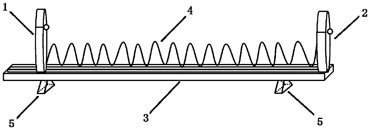
[0020] In order to solve the problem that the optical fiber is easily broken, shaken and tilted by using heavy objects in the optical fiber experiment in the prior art, the present invention provides an optical fiber uniform stress applying device, through the optical fiber clamp and the elastic deformation member moving along the linear slide rail , instead of the optical fiber rack and heavy objects in the prior art, it ensures that the stress on the optical fiber is continuous and uniform, so that the optical fiber does not break and is in a stable and reliable stretching state.

[0021] The present invention will be further described below in conjunction with accompanying drawing.

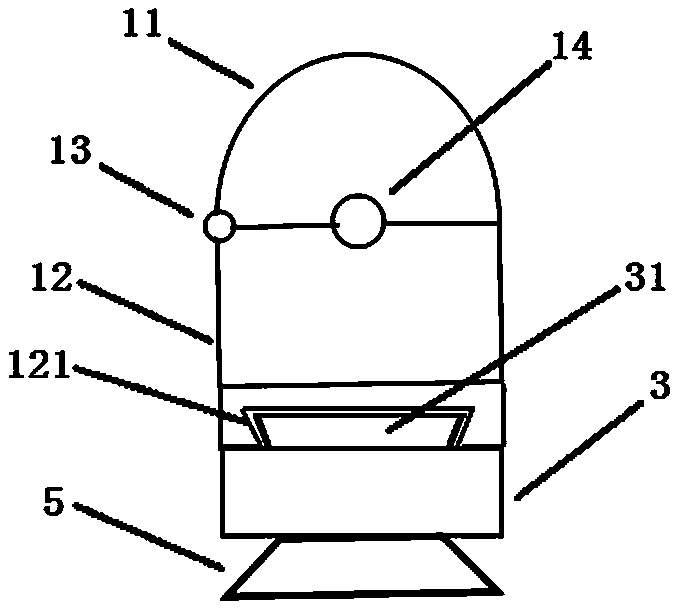
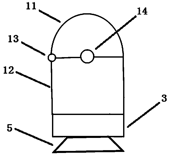
[0022] An optical fiber uniform stress application device, comprising an optical fiber clamp 1, an elastic deformation member 4, a fixed frame 2 and a linear slide rail 3, the optical fiber clamp 1 and the fixed frame 2 are respectively fixed at opposite ends of the linear slide rail 3, and the ...


PUM


Abstract

The invention relates to the technical field of optical fiber testing, and specifically discloses an optical fiber uniform stress application device, which includes an optical fiber clamp, an elastic deformation member, a fixing frame and a linear slide rail, and the optical fiber clamp and the fixing frame are respectively fixed on the linear sliding rail The two ends of the optical fiber clamp include a fiber clamping structure and a slider structure, which can clamp the optical fiber and slide on the linear slide rail. The two ends of the elastic deformation member are respectively fixed on the optical fiber clamp and the fixing frame. The fiber holder can be moved relative to the fixed frame on the linear slide rail. The invention can apply continuous and uniform stress to the optical fiber, so that the optical fiber is in a stable stretching state, avoiding the interference of the applied stress on the optical fiber communication, and ensuring the quality of the optical fiber test.

Description

technical field [0001] The invention relates to the technical field of optical fiber testing. Background technique [0002] Optical fiber is the abbreviation of optical fiber. Optical fiber communication is a communication method in which light waves are used as information carriers and optical fibers are used as transmission media. In order to study and improve the quality of optical fiber communication, it is necessary to do various optical experiments on optical fiber. In the experiment, the optical fiber is often required to be in a stretched state, so a certain uniform stress must be applied to the optical fiber. [0003] At present, there are various devices for applying stress to optical fibers. Most of them take a section of optical fiber in the built-up optical path, clamp one end on the optical fiber clamp, and place the other end flat on another optical fiber holder, and hang it next to the optical fiber clamp. A weight with a certain mass keeps the optical fib...

Claims


Application Information

Patent Timeline
Patent Type & Authority Patents(China)
IPC IPC(8): G02B6/26G02B7/00
CPCG02B7/00G02B6/26
Inventor 刘明生李燕许爱雪李国玉谢飞杨康
Owner SHIJIAZHUANG INST OF RAILWAY TECH
Why Eureka
Try Eureka