Micro-electro-mechanical system nuclear battery

A technology of micro-electromechanical systems and nuclear batteries, applied in piezoelectric devices/electrostrictive devices, circuits, piezoelectric/electrostrictive/magnetostrictive devices, etc., can solve problems such as limited electric energy and achieve efficient power supply

Active Publication Date: 2016-07-06
BOE TECH GRP CO LTD
View PDF4 Cites 4 Cited by
  • Summary
  • Abstract
  • Description
  • Claims
  • Application Information

AI Technical Summary

Problems solved by technology

[0005] However, the energy that can be converted by existing cantilever-beam nuclear batte

Method used


Image

  • Micro-electro-mechanical system nuclear battery
  • Micro-electro-mechanical system nuclear battery
  • Micro-electro-mechanical system nuclear battery

Examples


Embodiment Construction

[0026] The present invention will be specifically described below with reference to the accompanying drawings.

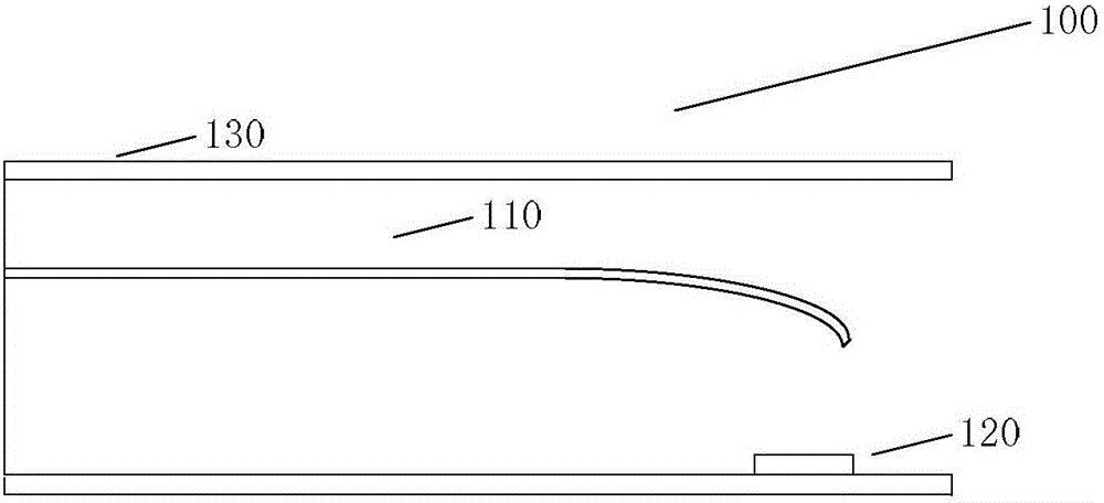
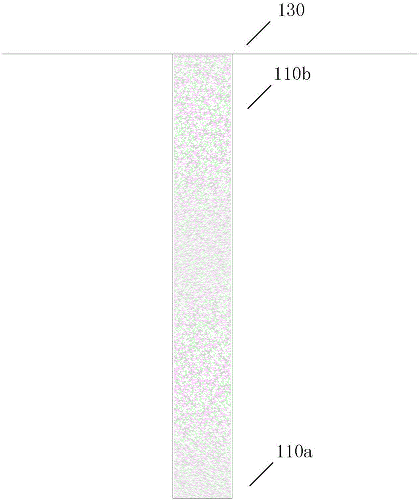
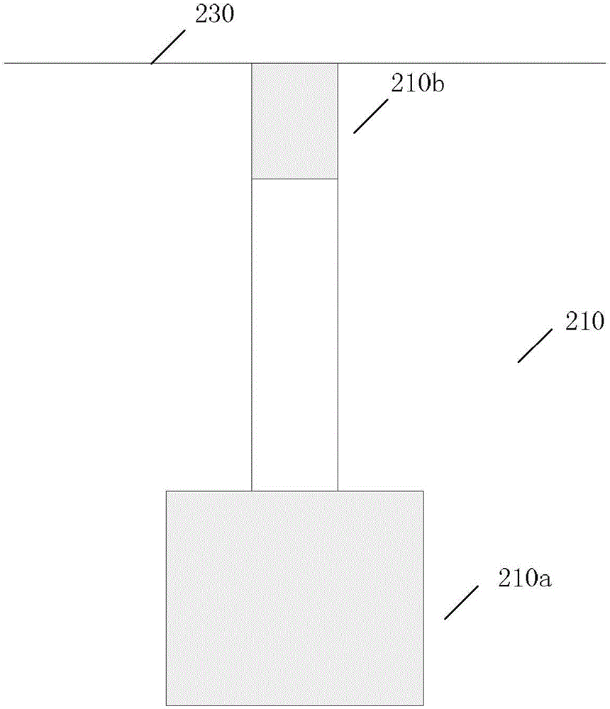
[0027] figure 2 A schematic diagram of the shape of the cantilever beam structure 210 in the MEMs nuclear battery 200 according to an embodiment of the present invention is shown. Other parts of the MEMs nuclear battery 200 according to the embodiment can refer to the structure shown in FIG. 1 .

[0028] Specifically, the MEMS nuclear battery 200 according to the embodiment includes a base 230 (only the side walls of the base are shown), a cantilever beam structure 210, and a radiation unit ( figure 2 not shown). The cantilever beam structure 210 is suspended and fixed to the side wall of the base through a fixed end. The cantilever beam structure 210 includes a radial portion 210a and a piezoelectric portion 210b. The radiation part 210 a is located at the free end of the cantilever beam structure 210 , and the piezoelectric part 210 b is located at the fixed...


PUM


Abstract

The invention discloses a micro-electro-mechanical system nuclear battery. The micro-electro-mechanical system nuclear battery comprises a substrate, a cantilever structure, and an emission unit; the cantilever structure is suspended in the air and is fixed on the side wall of the substrate through a fixing end; the cantilever structure comprises an emission portion and a piezoelectric portion; the emission portion is arranged on the free end of the cantilever structure; the piezoelectric portion is arranged on the fixing end of the cantilever structure; the emission unit is arranged on the position corresponding to the emission portion of the cantilever structure on the substrate for emitting electrons to the emission portion, wherein the width of the emission portion is greater than the width of the piezoelectric portion.

Description

technical field [0001] The invention relates to the field of micro-electro-mechanical systems, in particular to a micro-electro-mechanical system nuclear battery. Background technique [0002] With the development of science and technology, the size of various devices is getting smaller and smaller, and Micro-Electro-Mechanical Systems (MEMs, Micro-Electro-MechanicalSystem) are more and more widely used in many fields. However, the development of MEMs is limited by two factors, one is that MEMs lack the power of devices capable of remote operation, and the other is that the realization of MEMs requires power sources with high power density and long life. To solve these problems, various types of power sources have been tried to power MEMs, such as fossil fuels, solar energy, etc. But these types of power sources require recharging or refueling, which is difficult for MEMs. Moreover, these power sources have other drawbacks, such as the negative impact of fossil fuels on th...

Claims


Application Information

Patent Timeline
IPC IPC(8): G21H1/00B81B3/00
Inventor 王欣
Owner BOE TECH GRP CO LTD
Why Eureka
Try Eureka