A diaphragm type body cavity occlusion device
A membrane-type, body-cavity technology, applied in the field of medical devices, can solve the problems of uncertain shape of occluder, inconvenient operation and accurate placement, and unreported problems, so as to achieve reasonable setting of the number of spiral turns, balanced stone removal effect, and preparation The effect of easy crafting
- Summary
- Abstract
- Description
- Claims
- Application Information
AI Technical Summary
Problems solved by technology
Method used
Image
Examples
Embodiment 1
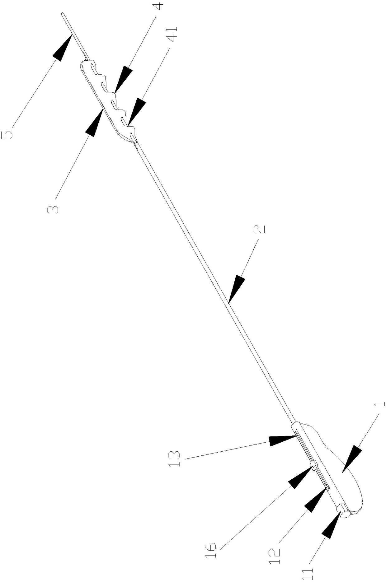
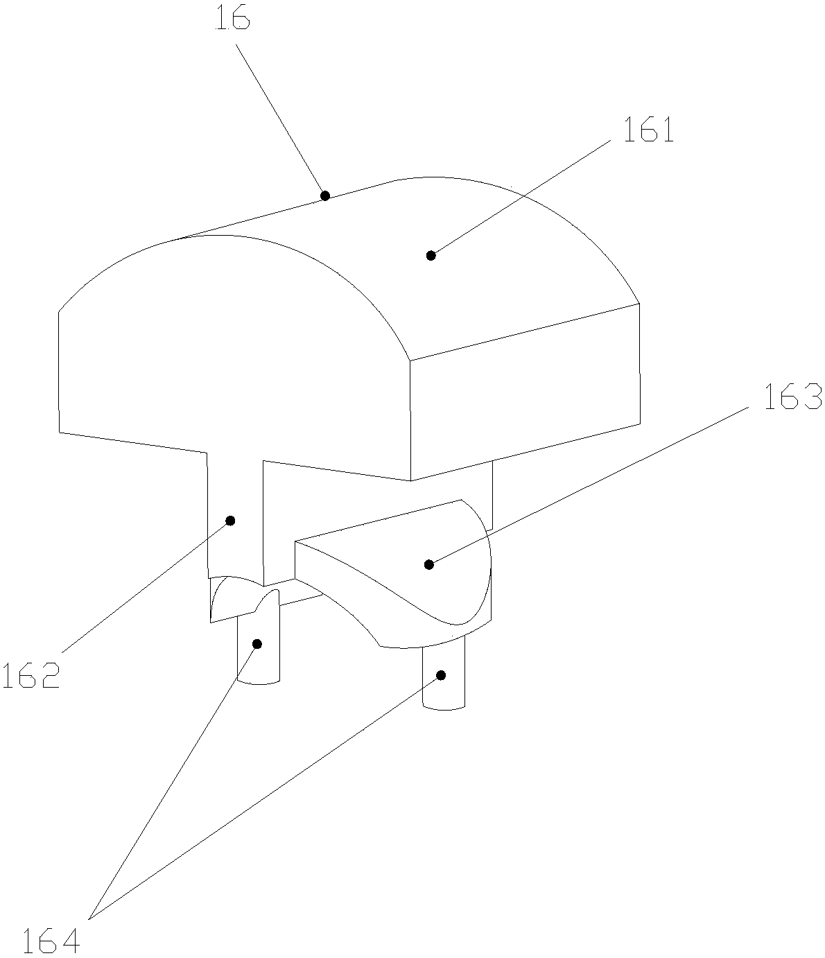
[0048] See figure 1 , figure 1 It is a structural schematic diagram of the membrane-type body cavity occlusion device of the present invention in a ready state. The diaphragm-type body cavity occlusion device is provided with a handle 1 , a handle 2 , a shaping wire 3 , a film 4 and an inner core 5 . The proximal end of the handle 1 is equipped with a limit cover 11 . The back side of the handle 1 is provided with a push handle installation hole 12 and a limit chute 13, and a push handle 16 is assembled in the limit chute 13.
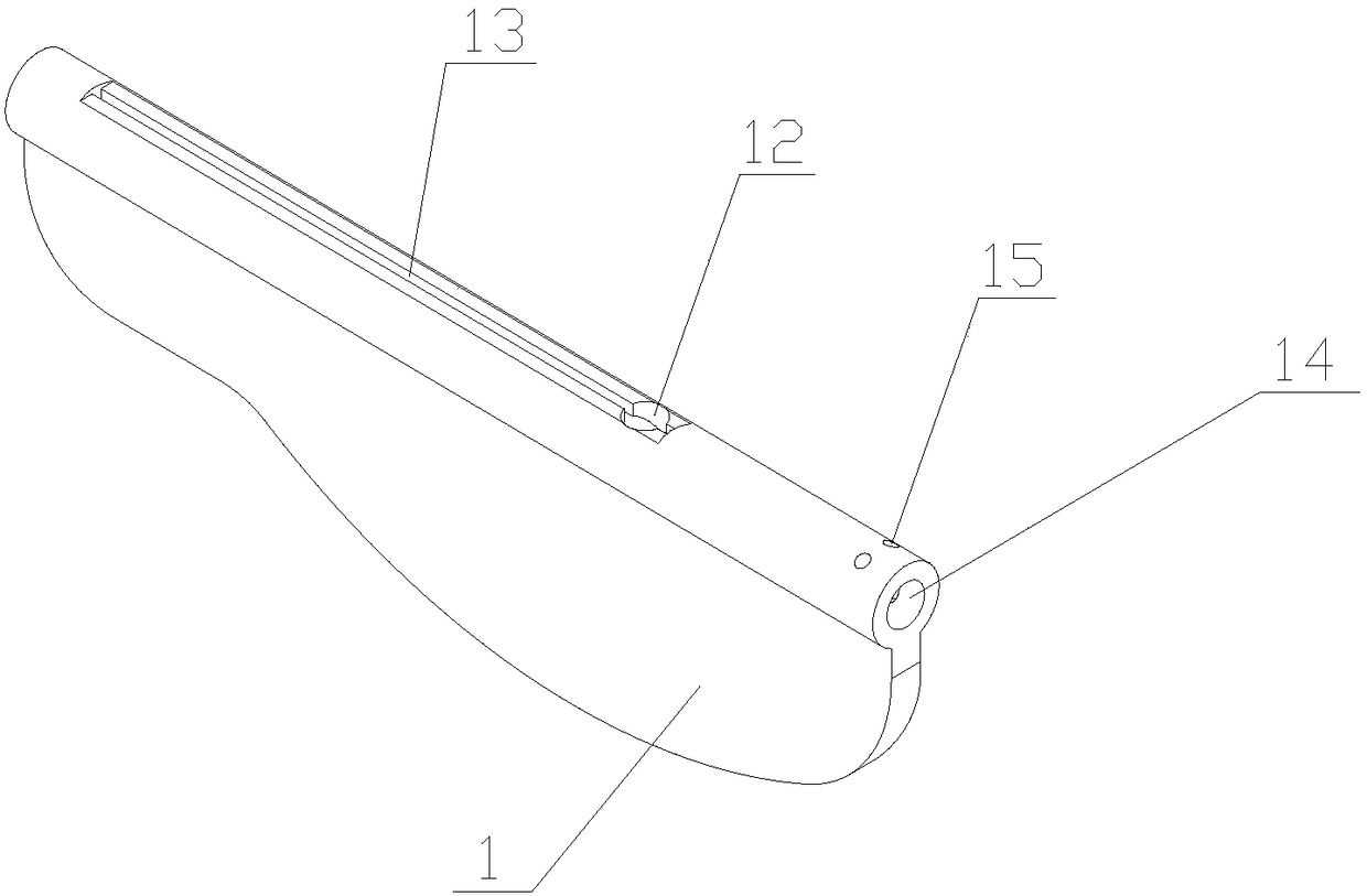
[0049] See figure 2 , figure 2It is a schematic diagram of the structure of the handle. The back side of the handle 1 is provided with a push handle installation hole 12 and a limit chute 13, the push handle installation hole 12 is located at the proximal end of the limit chute 13 and the two are connected. The handle 1 is provided with a mounting lumen 14 connecting the proximal end and the distal end. Two limit cover installation holes 15 are...
Embodiment 2
[0064] The membrane-type body cavity occlusion device of this embodiment is basically the same as that of Embodiment 1, the only difference lies in the shape of the membrane 4 . See Figure 7 , Figure 7 It is a schematic diagram of the structure of the membrane-type body cavity occlusion device in Example 2. The film 4 is a quadrilateral, wherein an axially linear edge has several through holes on the film along the side line direction, and the through holes Arranged in the axial direction, the inner core 5 passes through each through hole, and the film 4 and the inner core 5 can slide relatively; the other side opposite to the straight side of the film 4 is wrapped and fixed on the shaping wire 3 Above, the side length of the proximal side of the film 4 in the ready state is smaller than the side length of the far side. See Figure 8 , Figure 8 It is a schematic diagram of the structure of the diaphragm-type body cavity occlusion device in use in Example 2. In the use s...
Embodiment 3
[0066] The membrane-type body cavity occlusion device of this embodiment is basically the same as that of Embodiment 1, the only difference lies in the shape of the membrane 4 . See Figure 9 , Figure 9 It is a schematic diagram of the structure of the membrane-type body cavity occlusion device in Example 3. The film 4 is a quadrilateral, and one of the axially linear edges has several through holes on the film along the edge direction. The through holes Arranged in the axial direction, the inner core 5 passes through each through hole, and the film 4 and the inner core 5 can slide relatively; the other side opposite to the straight side of the film 4 is wrapped and fixed on the shaping wire 3 , and the edge is arc-shaped in the ready state. See Figure 10 , Figure 10 It is a schematic diagram of the structure of the diaphragm type body cavity occlusion device in use in Example 3. In the use state, the thin film 4 is spirally overlapped and arranged between the inner co...
PUM
 Abstract
Description
Claims
Application Information
 - R&D
- Intellectual Property
- Life Sciences
- Materials
- Tech Scout
- Unparalleled Data Quality
- Higher Quality Content
- 60% Fewer Hallucinations
Browse by: Latest US Patents, China's latest patents, Technical Efficacy Thesaurus, Application Domain, Technology Topic, Popular Technical Reports.
© 2025 PatSnap. All rights reserved.Legal|Privacy policy|Modern Slavery Act Transparency Statement|Sitemap|About US| Contact US: help@patsnap.com


