Numerical control system with cutter changing function and numerical control method of numerical control system

A technology of numerical control and numerical control device, applied in the direction of digital control, electrical program control, manufacturing tools, etc., can solve the problems of reduced tool change efficiency, increased machine tool cost, and increased processing time, so as to increase production capacity and improve changeover. Tool efficiency and the effect of reducing tool change time

Active Publication Date: 2016-07-13
新代科技(苏州)有限公司
View PDF12 Cites 6 Cited by
  • Summary
  • Abstract
  • Description
  • Claims
  • Application Information

AI Technical Summary

Problems solved by technology

However, during the tool change process of general machine tools, when the finished tool is pulled up to a positioning check point, the rising speed of the tool spindle must be reduced to 0 to confirm whether the positioning of the tool spindle is correct. Ensure that when the subsequent tool is retracted to the tool magazine, the tool can be accurately engaged with the latch of the tool magazine. Then, after confirming that the tool spindle has been positioned, the tool’s rising speed will accelerate from 0 again and rise to the safe point of tool change. It means that the tool has been stored in the tool magazine. After another tool is replaced, when the other tool descends to the positioning check point, it must also decelerate and then accelerate. Therefore, the time from the overall tool change process to machining can be greatly increased. , for this reason, shortening the tool change time is the problem that needs to be improved at present
[0003] Most of the ways to shorten the tool change time are achieved by improving the shape of the mechanism of the machine tool. However, because the mechanism must be designed according to various tool magazines, rather than in a universal form, the cost of the machine tool increases
Furthermore, the wear of the mechanism will increase with the use of time, so there will be some errors in the tool change process, which will lead to a decrease in tool change efficiency. It is quite limited to shorten the tool change time by improving the mechanism.

Method used


Image

  • Numerical control system with cutter changing function and numerical control method of numerical control system
  • Numerical control system with cutter changing function and numerical control method of numerical control system
  • Numerical control system with cutter changing function and numerical control method of numerical control system

Examples


Embodiment Construction

[0036] The present invention designs a numerical control system with a tool change function. The detector detects the rotation angle of the tool spindle, and the numerical control device generates a judgment signal after judging the rotation speed, position and rotation angle of the tool spindle. The numerical control device according to Judging the signal to plan the speed and rotation angle of the tool spindle and the position of the bearing shaft for tool change. When the numerical control system performs tool change, it can decide whether to stop the vertical pulling according to the actual movement of the tool, thus reducing the tool change time. The purpose of increasing production capacity and improving tool change efficiency.

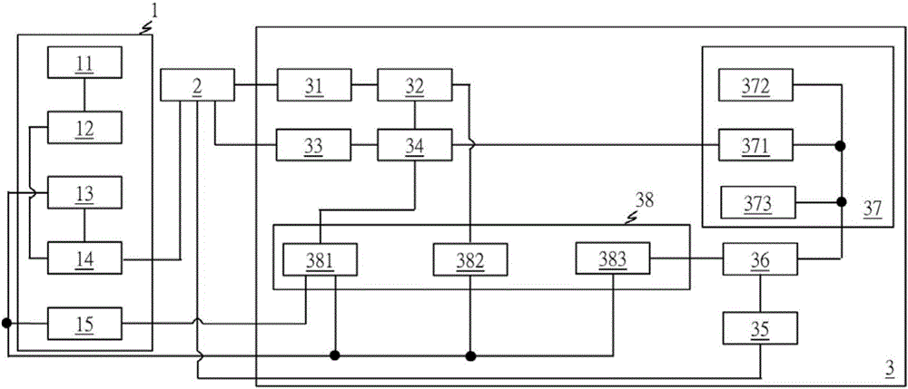
[0037] like figure 1As shown, the numerical control system with tool change function includes a numerical control device 1, a driving device 2 and a processing device 3, the driving device 2 has a first end, a second end, a third end and a fourt...


PUM


Abstract

The invention discloses a numerical control system with a cutter changing function and a numerical control method of the numerical control system. The numerical control system comprises a numerical control device, a driving device and a processing device. A detecting machine of the processing device detects the position of a cutter spindle in a Z-axis direction and the rotating angle of the cutter spindle, and outputs the rotating angle and the position information of the cutter spindle to the numerical control device; the numerical control device calculates out the rotating speed of the cutter spindle according to the rotating angle of the cutter spindle, generates a judgment signal after judging the rotating speed, the position and the rotating angle of the cutter spindle, and plans the rotating speed, the position and the rotating angle of the cutter spindle according to the judgment signal so as to perform cutter changing; when the numerical control system performs the cutter changing, the decision whether the operation of perpendicularly pulling up a cutter along a Z axis is stopped or not can be made according to the actual movement and rotation conditions of the cutter, so that the cutter changing time can be greatly shortened, the productivity is increased, and the cutter changing efficiency is improved.

Description

technical field [0001] The invention relates to a numerical control system with a tool changing function and a numerical control method thereof, belonging to the technical field of numerical control systems. Background technique [0002] When numerically controlled machine tools are used for machining, tools with different functions need to be used for machining due to different machining effects. Therefore, a tool change function is configured in the machine tool to achieve this purpose. However, during the tool change process of general machine tools, when the finished tool is pulled up to a positioning check point, the rising speed of the tool spindle must be reduced to 0 to confirm whether the positioning of the tool spindle is correct. Ensure that when the subsequent tool is retracted to the tool magazine, the tool can be accurately engaged with the latch of the tool magazine. Then, after confirming that the tool spindle has been positioned, the tool’s rising speed will...

Claims


Application Information

Patent Timeline
Patent Type & Authority Applications(China)
IPC IPC(8): B23Q3/157G05B19/18
CPCB23Q3/15713G05B19/18
Inventor 高仰逸许哲荣
Owner 新代科技(苏州)有限公司
Why Eureka
Try Eureka