Human-simulated finger with base joint and interphalangeal joint respectively and independently driven
An independently driven, joint-based technology, applied in the field of human-like fingers, can solve the problems of unable to move independently, unable to fully reproduce the dexterity of human hands, etc., to achieve the effect of beautiful grasping posture and improving dexterity
- Summary
- Abstract
- Description
- Claims
- Application Information
AI Technical Summary
Problems solved by technology
Method used
Image
Examples
specific Embodiment approach 1
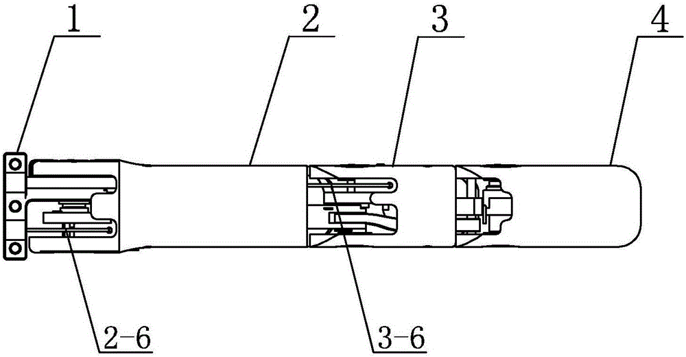
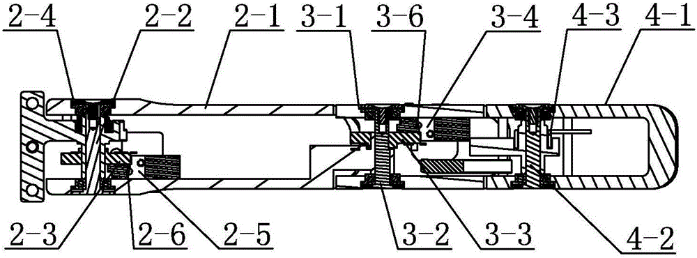
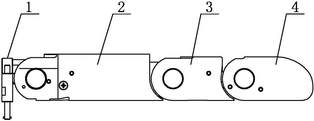
[0018] Embodiment 1: Combining figure 1 , figure 2 , image 3 and Figure 4 Describe this embodiment, this embodiment comprises finger base 1, near knuckle 2, middle knuckle 3, far knuckle 4 and four-bar linkage mechanism;
[0019] The proximal knuckle 2 includes a housing 2-1 for the proximal knuckle, a base joint 2-2, a potentiometer 2-3 for the base joint, a first torsion spring 2-4, a first pulley 2-5 and a first steel wire 2-6, one end of the finger base 1 is located in the proximal knuckle shell 2-1 and this end is hinged with the proximal knuckle shell 2-1 through the base joint 2-2, the finger base 1 The other end is arranged on the palm part, and the potentiometer 2-3 for the base joint is set outside the base joint 2-2 and connected with the shell 2-1 for the proximal knuckle and the base joint 2-2 respectively. The first torsion spring 2-4 is located in the shell 2-1 near the knuckle and is sleeved on the finger base 1, and the first pulley 2-5 is fixedly insta...
specific Embodiment approach 2
[0026] Specific implementation mode 2: Combining figure 1 , figure 2 , image 3 and Figure 4 Describe this embodiment, the far phalanx 4 described in this embodiment comprises far knuckle shell 4-1, DIP shaft 4-2, second torsion spring 4-3, torsion spring stop pin 4-4, middle phalanx shell 3-1 The end away from the finger base 1 is hinged in the far knuckle shell 4-1 through the DIP shaft 4-2, the second torsion spring 4-3 is set on the DIP shaft 4-2, and the torsion spring stop pin 4- 4. It is fixedly installed in the shell 4-1 for the far knuckle and is arranged close to the second torsion spring 4-3.
[0027] In the present invention, the proximal knuckle 2 and the middle knuckle 3 are independently driven, and the housing 2-1 for the proximal knuckle and the housing 4-1 for the far knuckle are respectively reset by the first torsion spring 2-4 and the second torsion spring 4-3 . In the present invention, the two ends of the MCP shaft, the two ends of the PIP shaft a...
specific Embodiment approach 3
[0028] Specific Embodiment 3: This embodiment is a further limitation of Specific Embodiment 2. The four-bar linkage mechanism described in this embodiment includes a connecting rod body 5-1 and two connecting rod pins 5-2. The connecting rod body 5-1 It is located in the shell 3-1 for the middle knuckle and its two ends are respectively connected with the shell 2-1 for the proximal knuckle and the shell 4-1 for the far knuckle. The end of the connecting rod body 5-1 close to the finger base 1 passes through a The connecting rod pin 5-2 is hinged on the proximal knuckle shell 2-1, and the end of the connecting rod body 5-1 away from the finger base 1 is hinged on the far knuckle through another connecting rod pin 5-2. On the shell 4-1.
PUM
 Abstract
Description
Claims
Application Information
 - R&D
- Intellectual Property
- Life Sciences
- Materials
- Tech Scout
- Unparalleled Data Quality
- Higher Quality Content
- 60% Fewer Hallucinations
Browse by: Latest US Patents, China's latest patents, Technical Efficacy Thesaurus, Application Domain, Technology Topic, Popular Technical Reports.
© 2025 PatSnap. All rights reserved.Legal|Privacy policy|Modern Slavery Act Transparency Statement|Sitemap|About US| Contact US: help@patsnap.com


