Supercharge Your Innovation With Domain-Expert AI Agents!

Cutter blade moving mechanism, cutter, and printer

一种移动机构、切割器的技术,应用在打印装置、印刷、印刷机等方向,达到抑制制造成本的效果

Inactive Publication Date: 2016-07-13
SEIKO EPSON CORP
View PDF6 Cites 3 Cited by
  • Summary
  • Abstract
  • Description
  • Claims
  • Application Information

AI Technical Summary

Problems solved by technology

However, in the structure in which the cutter blade is biased to the advanced position by the coil spring, there is a possibility that the movable blade may move to the advanced position due to vibration or the like.
Therefore, there is a problem in terms of security

Method used


Image

  • Cutter blade moving mechanism, cutter, and printer
  • Cutter blade moving mechanism, cutter, and printer
  • Cutter blade moving mechanism, cutter, and printer

Examples


Embodiment Construction

[0032] Hereinafter, a printer according to an embodiment of the present invention will be described with reference to the drawings.

[0033] (the whole frame)

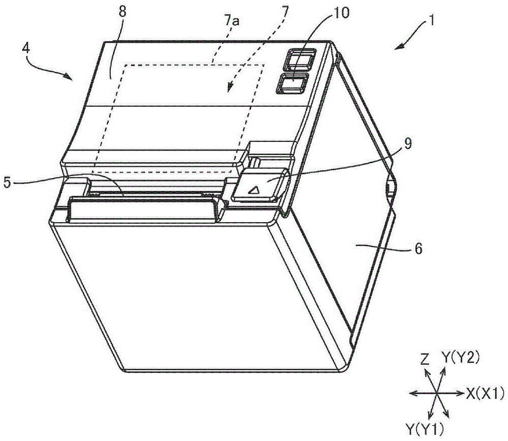
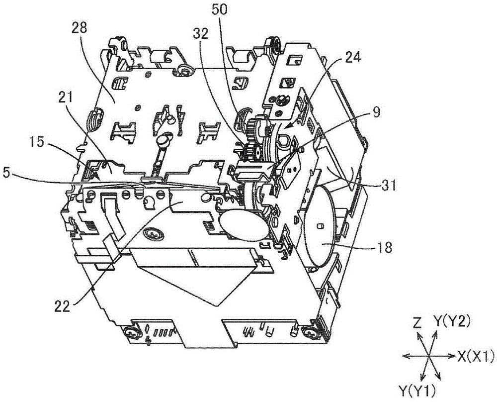
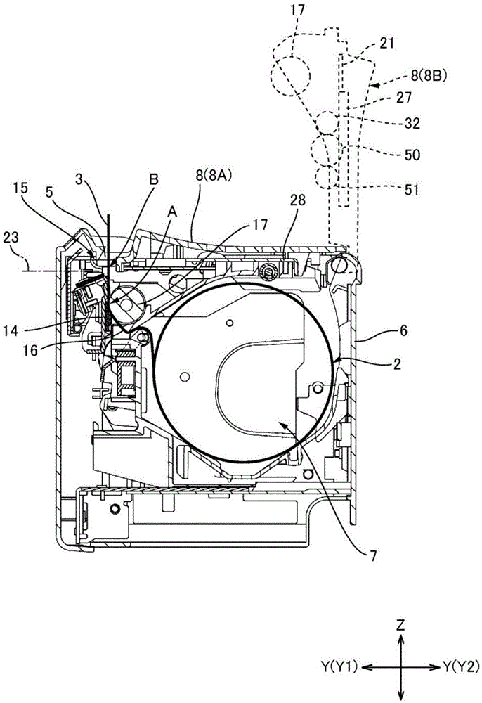
[0034] FIG. 1( a ) is a perspective view of a printer according to an embodiment of the present invention, and FIG. 1( b ) is a perspective view of the printer of FIG. 1 with its exterior removed. figure 2 is a schematic sectional view of the printer of FIG. 1 . The printer 1 of this example is a roll paper printer that prints on a strip of recording paper (sheet-shaped medium) 3 drawn from a roll paper 2 . As shown in FIG. 1 , the printer 1 includes a printer case 4 formed in a cubic shape as a whole. A discharge port 5 for discharging recording paper 3 is provided at a front portion of the upper surface of the printer housing 4 . The discharge port 5 extends in the width direction of the printer 1 . In addition, in the following, directions perpendicular to each other will be described as the printer width direct...


PUM


Abstract

A cutter blade moving mechanism moves a cutter blade to a forward position by a low output drive motor without an urging member urging the cutter blade to the forward position where media is cut. The first cutter blade moving mechanism 24 has a drive gear32 that moves the first cutter blade 21 forward and back; a drive motor31; and a compound gear40 to which rotation of the drive motor is transferred. The intermittent teeth part 43a of the compound gear meshes with a transfer gear51 after turning the compound gear is started by drive power from the drive motor, completing a rotation transfer path. Because there is a delay between when driving the drive motor starts and when the path transferring rotation from the drive motor to the drive gear is completed, rotational kinetic energy is stored in the compound gear during this delay. The transfer gear can therefore be turned with greater drive power (rotational kinetic energy) when the compound gear and transfer gear mesh.

Description

technical field [0001] The present invention relates to a cutter moving mechanism and a cutter that linearly move a cutter blade to cut a sheet-shaped medium. Moreover, it is related with the printer equipped with the said cutter. Background technique [0002] A printer equipped with a cutter is described in Patent Document 1. The cutter of this document is provided with a cutter blade moving mechanism that advances and retreats the cutter blade between an advanced position for cutting the recording paper and a retracted position separated from the advanced position. The cutter blade moving mechanism includes a drive motor, two cutter drive gears to which the drive force from the drive motor is transmitted, and a guide mechanism that guides the movable blade in the advancing and retreating direction. The two cutter drive gears are arranged in a direction perpendicular to the advancing and retreating direction of the movable blade with the rotation center axis facing in the...

Claims


Application Information

Patent Timeline
Patent Type & Authority Applications(China)
IPC IPC(8): B41F13/56B26D1/06B26D5/08
CPCB41J11/70B26D1/08F16H19/02F16H19/04B41F13/56B26D1/065B26D5/083B26D5/086
Inventor 西岛英昭石田彻吾成田浩士山田陆生
Owner SEIKO EPSON CORP
Features
  • R&D
  • Intellectual Property
  • Life Sciences
  • Materials
  • Tech Scout
  • Unparalleled Data Quality
  • Higher Quality Content
  • 60% Fewer Hallucinations
Learn More