A top beam and a hydraulic support comprising the top beam

A technology of roof beams and telescopic beams, applied to roof beams supporting mine roofs, mining equipment, earthwork drilling and mining, etc., can solve problems such as coal wall slabs, roof shedding, poor roof conditions, and low safety factors, and achieve Improve stability and reliability, avoid damage to the balance jack, and improve performance

Active Publication Date: 2018-01-12
SHANDONG LUNAN GRP ENERGY EQUIP MFG
View PDF10 Cites 0 Cited by
  • Summary
  • Abstract
  • Description
  • Claims
  • Application Information

AI Technical Summary

Problems solved by technology

[0003] At present, the following problems still exist in the use of hydraulic supports: 1. After the shearer has finished mining coal, the phenomenon of coal wall and roof falling off often occurs, which directly affects the safety and efficiency of the coal mining face, especially large 2. The support strength cannot meet the needs of actual work, and the safety factor is low; 3. The angle between the cover beam and the top beam often exceeds the limit angle due to reasons such as poor roof conditions and operational errors, causing damage to the balance jack and causing The hydraulic support has a poor support effect on the roof, and the maintenance cost of the equipment is high; 4. Due to the extension and retraction of the telescopic beam, the front end plate and web of the roof beam are open-welded, etc.

Method used


Image

  • A top beam and a hydraulic support comprising the top beam
  • A top beam and a hydraulic support comprising the top beam
  • A top beam and a hydraulic support comprising the top beam

Examples


Embodiment 1

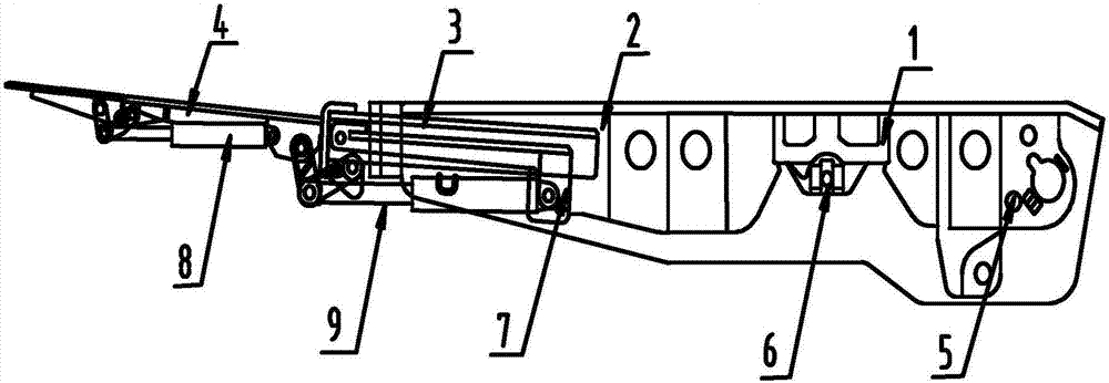
[0033] Such as Figure 1-2 As shown, a top beam is provided with a telescopic beam 3 inside, one end of the top beam is set as a box structure 1, and the other end is set as a cavity structure 2, and a limit mechanism is set at the box structure 1 5. The limit mechanism 5 is set as a limit block, the limit block is located at the bottom of the top beam, and the limit block is located at the height of 1 / 4-1 / 3 of the top beam, and the top beam and A balance jack is arranged between the cover beams. When the hydraulic support is at the highest position, the limit mechanism 5 limits the angle between the cover beam and the top beam, which can effectively avoid damage to the balance jack and strengthen the hydraulic support. It can effectively support the roof and reduce equipment maintenance costs.

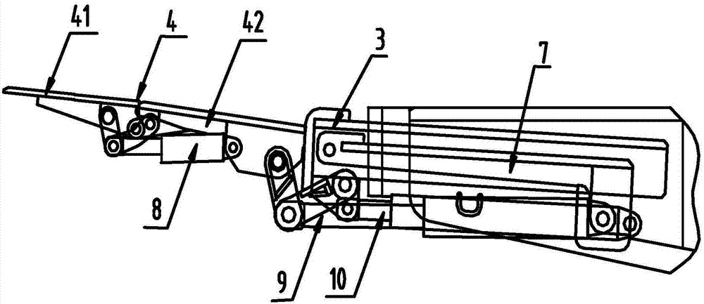
[0034] The cavity structure 2 is provided with a side protection mechanism 4, and the side protection mechanism 4 includes a first-level side protection board 41 and a second-level s...

Embodiment 2

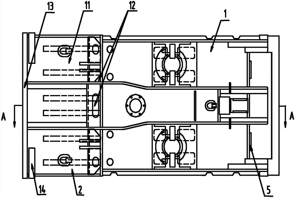
[0038] Such as Figure 2-4As shown, the cavity structure 2 includes at least one chamber 11. In this embodiment, the cavity structure 2 is set as a five-chamber structure, and the telescopic beam 3 is located in the cavity 11. The cavity structure 2 The bottom is provided with a coal drop hole 12, and the coal powder brought into the top beam by the telescopic beam 3 during the extension and retraction operation can be discharged through the coal drop hole 12 to improve the performance of the hydraulic support. The coal drop hole 12 Set as one or several combinations of common geometric figures, preferably, the coal drop holes 12 located at the corners of the cavity structure 2 are set to polygonal structures, such as triangles, squares or rectangles, etc., which help to reduce the dead ends of coal drop , The diameter of the circumscribed circle of the coal drop hole 12 is 8-12mm, and the size of the coal drop hole 12 is optimized to ensure that the strength of the top beam m...

Embodiment 3

[0042] Such as Figure 1-6 As shown, a hydraulic support includes the above-mentioned top beam, and the specific working process of the hydraulic support is as follows:

[0043] Firstly, through the anti-falling device, the top beams of different hydraulic supports are connected to enhance the overall stability;

[0044] Secondly, the lifting operation is performed, and when the hydraulic support reaches the highest position, the limit mechanism 5 limits the angle between the top beam and the shield beam;

[0045] Again, according to the needs of the actual fully mechanized mining face, start the telescopic beam jack 10, the jack 2 9 and the jack 1 8 respectively to realize the extension of the telescopic beam 3, the secondary side guard 42 and the primary side guard 41. Exit / retract operation, change support area.


PUM


Abstract

The invention relates to a top beam and a hydraulic bracket with the top beam, and belongs to the technical field of coal mine equipment. The top beam is internally provided with a telescopic beam; one end of the top beam is of a box body structure; the other end of the top beam is of a cavity structure; a side protecting mechanism is arranged at the cavity structure; coal falling holes are formed in the bottom of the cavity structure; and a flow-up limiting mechanism is arranged at the telescopic beam. The top beam has the characteristics of stability, high reliability, low equipment repairing expense, good practicability, tight contact with a top plate and long service life.

Description

technical field [0001] The invention belongs to the technical field of coal mine equipment, and in particular relates to a top beam and a hydraulic support including the top beam. Background technique [0002] Hydraulic support is a kind of hydraulic power device that uses liquid pressure to generate support force and realizes automatic shifting for roof support and management. It is an indispensable supporting equipment for comprehensive mechanized coal mining. Mining face mine pressure acts on the hydraulic support in the form of external load. Since the mid-1990s, my country's hydraulic supports have entered a stage of rapid development. During this period, fully mechanized mining technology was promoted, and the number of fully mechanized mining working faces in the country has been greatly increased. At the same time, the performance, technical parameters, stability and reliability of hydraulic supports have also been significantly improved, and the types of supports h...

Claims


Application Information

Patent Timeline
Patent Type & Authority Patents(China)
IPC IPC(8): E21D17/00E21D17/02E21D17/10E21D17/05
CPCE21D17/00E21D17/02E21D17/0206E21D17/04E21D17/10
Inventor 靖大鹏李福祥梁开东张严敬徐亚军李宪庆严孝伟李云海崔振盛波陈琥
Owner SHANDONG LUNAN GRP ENERGY EQUIP MFG
Why Eureka
Try Eureka