Stainless-steel ultrasonic water meter

An ultrasonic and stainless steel technology, applied in the field of stainless steel ultrasonic water meters, to achieve the effect of beautiful appearance, accurate measurement and long service life

Inactive Publication Date: 2016-07-13
HARBIN SHENGCHANG TECH DEV
View PDF8 Cites 8 Cited by
  • Summary
  • Abstract
  • Description
  • Claims
  • Application Information

AI Technical Summary

Problems solved by technology

[0003] The present invention is to solve the problem of various disadvantages of the mechanical wat

Method used


Image

  • Stainless-steel ultrasonic water meter
  • Stainless-steel ultrasonic water meter
  • Stainless-steel ultrasonic water meter

Examples


specific Embodiment approach 1

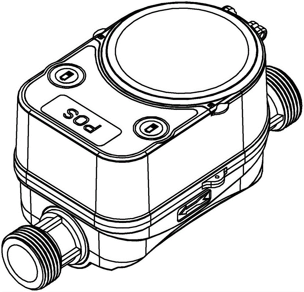
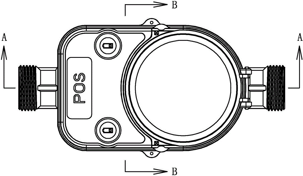
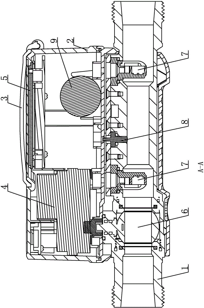
[0018] Specific implementation mode one: refer to Figure 1 to Figure 6 Specifically explain this embodiment, the stainless steel ultrasonic water meter described in this embodiment, it includes: stainless steel ultrasonic base meter 1, stainless steel shell 2, wireless transmission circuit one, wireless transmission circuit two, motor 4, main circuit 5, ultrasonic transducer 7. Temperature sensor 8, battery one 9 and battery two 10;

[0019] There are three openings on the side wall of the stainless steel ultrasonic base meter 1, and the two ultrasonic facing ends of the ultrasonic transducer 7 and the temperature measuring end of the temperature sensor 8 respectively pass through the three openings and are located inside the stainless steel ultrasonic base meter 1, and the The opening where it is located is sealed, and the two ultrasonic opposing ends of the ultrasonic transducer 7 face each other, and the temperature measuring end of the temperature sensor 8 is used to coll...

specific Embodiment approach 2

[0028] Specific implementation mode two: refer to Figure 5 Describe this embodiment in detail. This embodiment is to further describe the stainless steel ultrasonic water meter described in Embodiment 1. In this embodiment, the two ultrasonic waves of the ultrasonic transducer 7 and the temperature measuring end of the temperature sensor 8 The openings are sealed by sealing rings 11 respectively.

[0029] The sealing ring 11 is to prevent water from leaking from the stainless steel ultrasonic base meter 1 and is installed in the gap between the ball valve 6, the ultrasonic transducer 7 and the temperature sensor 8 and the stainless steel ultrasonic base meter 1, as attached Figure 5 shown.

specific Embodiment approach 3

[0030] Embodiment 3: This embodiment is to further explain the stainless steel ultrasonic water meter described in Embodiment 1. In this embodiment, battery one 9 is an ER26500H lithium battery, and battery two 10 is an ER18505M lithium battery.


PUM


Abstract

The invention discloses a stainless-steel ultrasonic water meter, and relates to the field of water meters. The stainless-steel ultrasonic water meter aims at solving the problem that multiple defects exist in a mechanical water meter used by an existing inhabitant. According to the stainless-steel ultrasonic water meter, the ultrasonic time difference principle is adopted, a full-electronic water meter made by industrial-grade electronic components is adopted, and compared with a mechanical water meter, the full-electronic water meter has the advantages that accuracy is high, reliability is good, the range ratio is wide, the service life is long, no moving part exists, parameters do not need to be set, and installing is carried out at any angle. On the basis of the metering mode of the ultrasonic water meter, the wireless collecting and reading characteristic and the valve control characteristic are also added. A pair of ultrasonic transducers are applied to receiving and sending ultrasonic waves at a flow measurement part in the opposite directions, the flow velocity of fluid is indirectly measured by observing the propagation time difference of downstream and upstream of the ultrasonic waves in a medium, and then the flow is calculated through the flow velocity. The stainless-steel ultrasonic water meter is high in measuring accuracy, convenient to use and prone to digital management; compared with water meters made of existing materials, the water quality is guaranteed; the stainless-steel ultrasonic water meter is suitable for measuring the water yield of a tap water pipe.

Description

technical field [0001] The invention belongs to the field of water meters, in particular to a stainless steel ultrasonic water meter. Background technique [0002] Water meters are necessary equipment for every household. At present, all households use mechanical water meters, and settle fees according to the instructions of the water meters. However, there are many disputes and disadvantages that are difficult to solve when using the existing mechanical water meters for settlement. For example: the accuracy of the thermal energy meter is reduced due to the severe wear and tear of the mechanical water meter for many years, which in turn requires the user to pay for maintenance many times, resulting in difficult disputes between the user and the water company; the staff of the water company regularly knock on the door of the user to check the water meter Flow data, meter reading success and accuracy are low, and the management cost of the water company is too high, time-consu...

Claims


Application Information

Patent Timeline
IPC IPC(8): G01F1/66
CPCG01F1/66G01F1/662
Inventor 崔崇民
Owner HARBIN SHENGCHANG TECH DEV
Why Eureka
Try Eureka