Experiment loading device for realizing large-size model multipoint load distribution

A loading device, large-scale technology, applied in the direction of measuring devices, machine/structural component testing, instruments, etc., can solve the problems of uneven load, time-consuming, uneconomical design, etc., to reduce the number of load-bearing frames and jacks, The effect of high material utilization and economy, and simplified test loading process

Inactive Publication Date: 2016-07-13
TSINGHUA UNIV +2
View PDF9 Cites 4 Cited by
  • Summary
  • Abstract
  • Description
  • Claims
  • Application Information

AI Technical Summary

Problems solved by technology

[0003] The problems of the first method are: (1) For the large-scale grid cylinder, its plane size is still large even after being scaled down, which makes it difficult for the rigid loading plate to achieve true rigidity, or the huge amount of steel used leads to an uneconomical design; ( 2) Due to the large plane size of the large grid tube, the load on the top of the grid tube is not uniform, and may even vary greatly and irregularly, while the rigid loading plate cannot obtain the specified load distribution effect
[0004] The problems in the second method are: (1) multiple sets of loading equipment are arranged along the periphery of the grid cylinder, which requires a large area of ​​test site; (2) each set of loading equipment needs load-bearing frames and jacks, and the quantity is large, which may be difficult for the laboratory to test. (3) The loads imposed by each jack are different, and multi-point loading brings problems such as difficult coordination, large demand for human resources, and long time consumption
[0005] Therefore, the current conventional loading methods are difficult to meet the needs of the stability test of large grid cylinders, and it is urgent to find other efficient loading methods

Method used


Image

  • Experiment loading device for realizing large-size model multipoint load distribution
  • Experiment loading device for realizing large-size model multipoint load distribution
  • Experiment loading device for realizing large-size model multipoint load distribution

Examples


Embodiment Construction

[0025] Attached below Figure 1-9 , to describe the implementation of the present invention in detail.

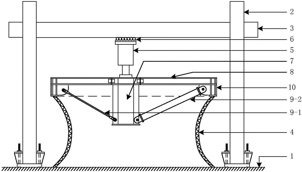
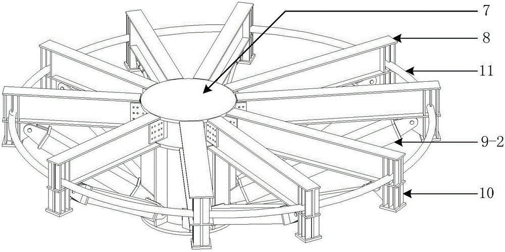
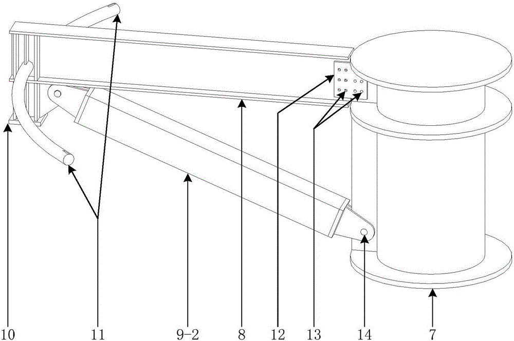
[0026] Such as Figure 1~2 As shown, a test loading device capable of realizing multi-point load distribution of large-scale models includes the following components:

[0027] 1——Test bench;

[0028] 2——bearing column;

[0029] 3 - bearing beam;

[0030] 4——Large grid cylinder test specimen;

[0031] 5 - Jack;

[0032] 6——horizontal sliding support;

[0033] 7 - fly column;

[0034] 8—radial beam;

[0035] 9—diagonal tie rod, including two forms: 9-1—high strength steel tie rod, 9-2—section steel or welded section member;

[0036] 10——load short column;

[0037] 11—circular support.

[0038] Such as figure 1 As shown, the test loading device capable of realizing multi-point load distribution of a large-scale model is composed of a bearing system, a loading system and a load distribution system. The load-bearing system includes a test bench 1, a load-bearing col...


PUM


Abstract

The invention relates to an experiment loading device for realizing large-size model multipoint load distribution, and belongs to the technical field of architectural structure. The experiment loading device is formed by a bearing system, a loading system and a load distribution system. The load distribution system of which main body is a space radiation type beam string structure can make a jack to act on the load of middle fly column, according to the rigidity of a radial directional beam and a diagonal draw bar in radiation directions, the force can be automatically and precisely distribute to load points of an experimental sample, so that the multipoint load is simplified into single-point load, the number of heavy frames and jacks needed by the experiment is decreased, the needed experiment site area is decreased, the experiment loading process is simplified, the experiment time consumption is reduced, and the experiment cost is reduced at last.

Description

technical field [0001] The invention relates to a test loading device, in particular to a test loading device capable of realizing multi-point load distribution of a large-scale model, and belongs to the technical field of building structures. Background technique [0002] Due to their beautiful appearance, wide internal use space and good mechanical properties, large-scale cylindrical grid tubes and hyperboloid grid tubes have been more and more engineering applications in recent years. As a new type of structure, when it is subjected to axial pressure, its failure mode is dominated by instability, and scaled-scale model tests are required in engineering applications. At present, there are two conventional loading methods for the stability test of the scale model of the grid cylinder: the first is to set a rigid loading plate on the top of the grid cylinder, and apply load to the rigid loading plate; the second is to place a load on the grid cylinder Loading at multiple po...

Claims


Application Information

Patent Timeline
Patent Type & Authority Applications(China)
IPC IPC(8): G01M99/00
CPCG01M99/007
Inventor 郭彦林章友浩朱博莉胡正平李霆王海山徐敏王再胜汤海江秦成文
Owner TSINGHUA UNIV
Why Eureka
Try Eureka