A stress loading device

A technology of stress loading and loading cabin, which is applied in the direction of measuring devices, using stable tension/pressure testing material strength, instruments, etc., which can solve the problem of inability to faithfully simulate the uneven stress state of the model, and the large deformation of the model, loading Problems such as small model size to achieve the effect of ensuring control and measurement accuracy, convenient installation and manufacture, and overcoming load hysteresis

Active Publication Date: 2018-04-03
CHONGQING UNIV
View PDF9 Cites 0 Cited by
  • Summary
  • Abstract
  • Description
  • Claims
  • Application Information

AI Technical Summary

Problems solved by technology

The disadvantages of the above two loading methods are also gradually exposed: (1) the force in each direction of triaxial loading can only be a whole, and the uneven force state of the model in the same direction cannot be faithfully simulated; (2) loading with flexible rubber , the loading uniformity is acceptable, but its stroke is small and the load intensity is low, which cannot meet the large deformation and high strength requirements of the model, and the scope of application is greatly limited; it cannot be recycled and practical, the cost is high, and the loading The size of the model is generally small (all less than 1 cubic meter), and the simulation can be realized in the case of relatively simple geological environmental conditions, but it cannot fully simulate the situation of more complex geological conditions

Method used


Image

  • A stress loading device
  • A stress loading device
  • A stress loading device

Examples


Embodiment Construction

[0022] The present invention will be further described below in conjunction with the accompanying drawings and embodiments.

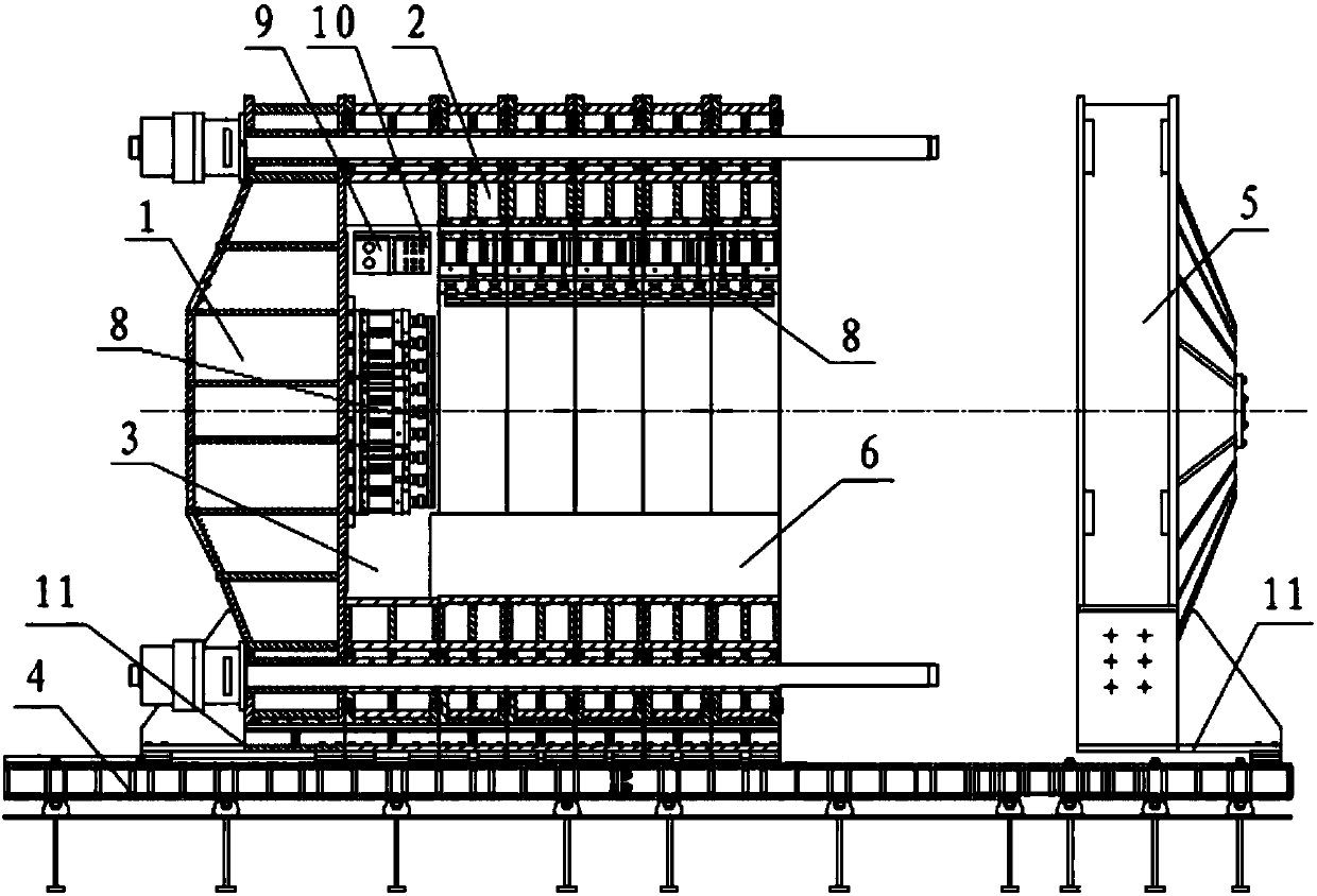
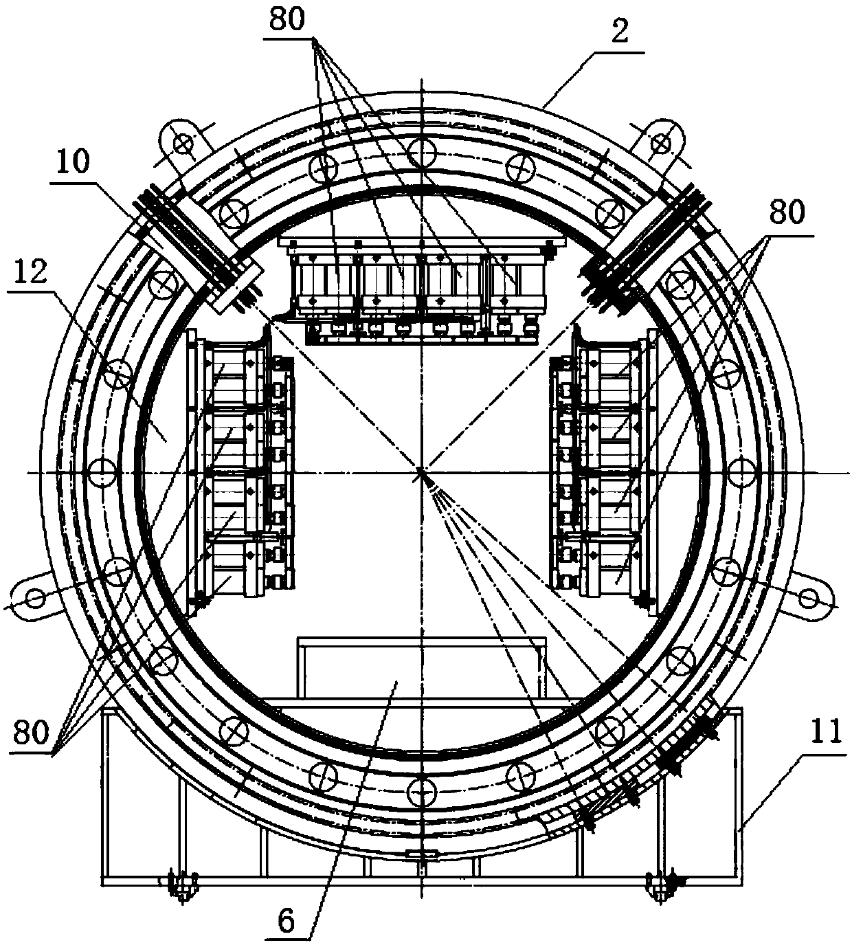
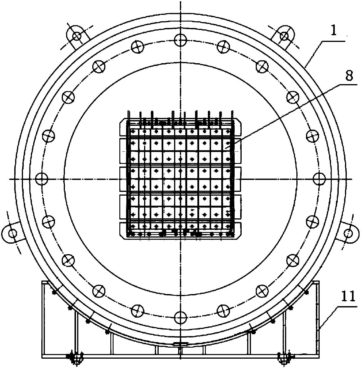
[0023] A stress loading device, including a loading chamber for pressurizing the model used in the experiment, the loading chamber is an oil pressure type, and it is connected with a hydraulic control system and a servo oil source for pressure application and pressure release control. The loading cabin is integrally arranged on a base 4, which includes an axially horizontal rear loading cover 1, an annular loading frame and a front reaction cover 5, and a test piece platform 6 for horizontally holding the model is arranged on the bottom side of the annular loading frame. A uniform loader 8 is arranged horizontally on the left side of the ring loading frame facing right, a uniform loader 8 is arranged horizontally on the right side of the ring loading frame facing left, and a uniform loader 8 is arranged vertically downward on the upper side of the ring l...


PUM


Abstract

The invention relates to a stress loading device. The stress loading device comprises a loading cabin, a hydraulic control system and a servo oil source; the loading cabin comprises an axial horizontal rear loading cover, an annular loading frame and a front counter-force cover; a test piece platform for horizontally bearing a model is arranged on the bottom side in the annular loading cabin frame; uniformly distributed loader arrays which are used for applying stress are arranged on the left side, the right side and the upper side, opposite to the left surface, the right surface and the upper surface of the model, in the annular loading frame; uniformly distributed loader arrays are arranged in the axial direction, opposite to the rear surface of the model, of the rear loading cover; a front counter-force plate is arranged in the axial direction, opposite to the front surface of the model, of the front counter-force cover. The uniformly distributed loaders in the loading cabin are connected with the servo oil source; a displacement sensor and an oil pressure sensor are arranged in the loading cabin; the displacement sensor and the oil pressure sensor are connected with a hydraulic control system. The annular loading frame is detachably connected with the rear loading cover and the front counter-force cover in a sealed manner. The device can apply a variety of modes of stress to the models with different sizes.

Description

technical field [0001] The invention relates to geomechanics model test loading equipment, in particular to a stress loading device for coal and rock engineering simulation experiments. Background technique [0002] The model loading system is a key technology in the geomechanics model test, because it is directly related to the simulation effect and accuracy, and also directly affects the similarity of the stress (strain) field formed in the model block. It plays a vital role in whether the model test results can conform to the actual stress state of the project. [0003] In the existing model loading technology, the following two loading methods are commonly used: one is to use a true three-axis loading system to load the model, such as the high ground stress true three-dimensional loading model test system disclosed in CN 101285808 B; the other is to use a flexible rubber The bladder is loaded to the model, such as the high-stress flexible loading instant unloading test ...

Claims


Application Information

Patent Timeline
Patent Type & Authority Patents(China)
IPC IPC(8): G01N3/02G01N3/12
CPCG01N3/02G01N3/12
Inventor 夏彬伟卢义玉李晓红明治清刘承伟汤积仁郭世杰张旋
Owner CHONGQING UNIV
Why Eureka
Try Eureka