Lens and imaging device

An imaging device and lens technology, applied in the field of optical lenses, can solve the problems of optical center separation, low signal-to-noise ratio, and avoid ghosting, and achieve the effects of consistent imaging illumination, improved signal-to-noise ratio, and reduced degradation.

Active Publication Date: 2016-07-13
BEIJING MADV TECH CO LTD +1
View PDF10 Cites 18 Cited by
  • Summary
  • Abstract
  • Description
  • Claims
  • Application Information

AI Technical Summary

Problems solved by technology

[0003] However, the use of two wide-angle lenses with a field of view larger than 180 degrees will inevitably lead to the problem of separation of optical centers, which will degrade the image in the overlapping area of ​​the image
Moreover, the farther the two wide-angle lenses are from each other in the direction of the optical axis, the more obvious the degradation of the overlapping part of the image will be.
[0004] In addition, the inventor of the present invention found in the process of implementing the invention that most wide-angle lens structures exceeding 180 degrees of field of view often have vignetting at the large field of view, so that the field of view light cannot fill the entire field of view; The wide-angle lens with a wide-angle field of view does not consider the formation of ghost images in structure, and does not avoid the formation of ghost images in structural design, and the signal-to-noise ratio is relatively low

Method used


Image

  • Lens and imaging device
  • Lens and imaging device
  • Lens and imaging device

Examples


Embodiment Construction

[0045] In order to express the technical solutions and advantages of the embodiments of the present invention more clearly, the technical solutions of the present invention will be described in further detail below through the accompanying drawings and examples. The following examples are used to illustrate the application, but not to limit the application range.

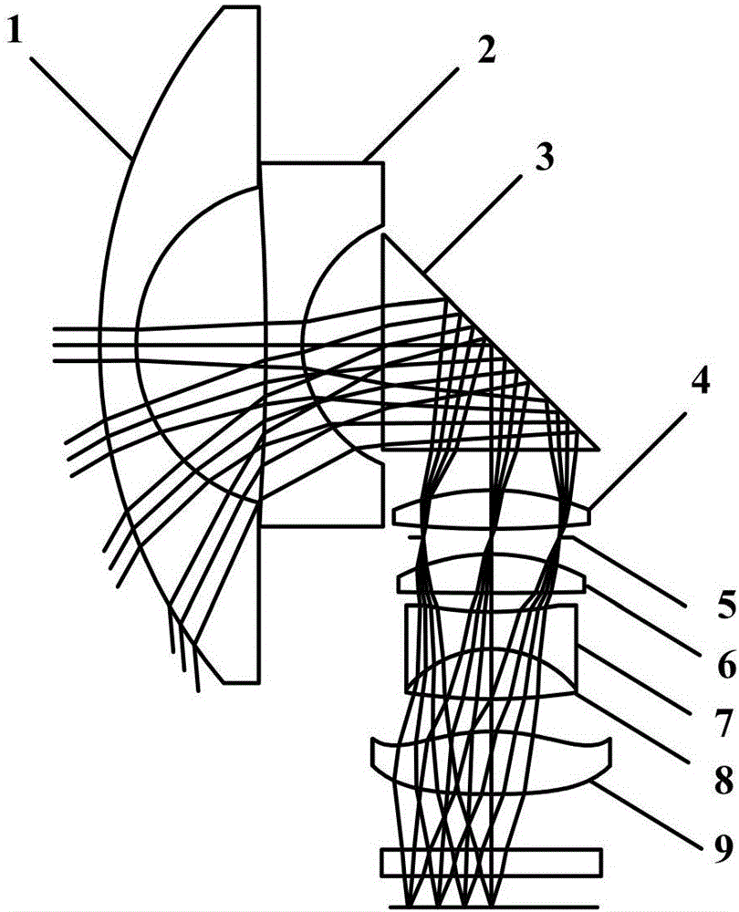
[0046] figure 1 It is a schematic structural diagram of a lens provided according to an embodiment of the present invention. The lens includes: a front lens group, a rear lens group, a reflective element and a diaphragm. Such as figure 1 As shown, the lens includes in sequence from the object side to the image side: a first lens 1, a second lens 2, a reflective element 3, a third lens 4, a diaphragm 5, a fourth lens 6, a fifth lens 7, and a sixth lens 8 and the seventh lens 9 .

[0047] Wherein, the front lens group includes: a first lens 1 and a second lens 2 , and the rear lens group includes: a third lens 4 ,...


PUM


Abstract

The invention discloses a lens and an imaging device.The lens comprises a front lens set close to an object space, a reflecting element, a diaphragm and a rear lens set close to an image space.The front lens set comprises a first lens body and a second lens body.The rear lens set comprises a third lens body, a fourth lens body, a fifth lens body, a sixth lens body and a seventh lens body.The front lens set is a negative-refractive-index lens set.The rear lens set is a positive-refractive-index lens set.The reflecting element is arranged between the second lens body and the third lens body.The diaphragm is arranged between the third lens body and the fourth lens body.According to the lens and the imaging device, vignetting is avoided due to a large view field, imaging illumiance is consistent on the view field, scene light intensity energy can be absorbed to the maximum extent, meanwhile, a parasitic light forming light path is considered in the lens, ghosts generated by the lens bodies are removed by controlling the structure of the lens, and the signal to clutter ratio of a system is increased.

Description

technical field [0001] The invention relates to the technical field of optical lenses, in particular to a lens and an imaging device. Background technique [0002] At present, to obtain full spatial information, two imaging optical systems that face each other or are staggered can be used. Each optical system includes a wide-angle lens with a field of view greater than 180 degrees and an imaging sensor device that matches the wide-angle lens. The image information in all directions is simultaneously obtained through the two imaging optical systems, and the image information of 4π solid angle full space is formed by unfolding and splicing of the overlapping areas. [0003] However, the use of two wide-angle lenses with a field of view larger than 180 degrees will inevitably lead to the problem of separation of optical centers, and the separation of optical centers will degrade the image in the overlapping area of ​​the image. Moreover, the farther the distance between the tw...

Claims


Application Information

Patent Timeline
Patent Type & Authority Applications(China)
IPC IPC(8): G02B13/00G02B13/06G03B37/00
CPCG02B13/0015G02B13/06G03B37/00G02B27/0018G03B17/17G03B37/04
Inventor 宋维涛黄业桃刘绪明曾吉勇
Owner BEIJING MADV TECH CO LTD
Why Eureka
Try Eureka