Medium wave infrared image space scanning optical system having oscillating mirror

An optical system and infrared technology, applied in the field of scanning optics, can solve the problem of no reduction in the load of the two-dimensional turntable, and achieve the effect of reducing the volume and weight, reducing the complexity and increasing the scanning speed.

Inactive Publication Date: 2016-07-13
BEIJING AEROSPACE INST FOR METROLOGY & MEASUREMENT TECH +1
View PDF3 Cites 2 Cited by
  • Summary
  • Abstract
  • Description
  • Claims
  • Application Information

AI Technical Summary

Problems solved by technology

This form is the basic form of image square scanning. Although the system aperture is reduced, the load on the two-dimensional turntable is not reduced, and it is still the cooling detector and the rear imaging lens.

Method used


Image

  • Medium wave infrared image space scanning optical system having oscillating mirror

Examples


Embodiment Construction

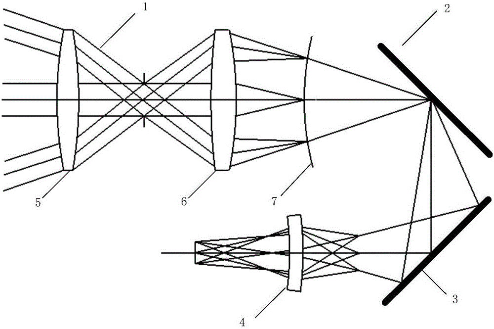
[0012] Mid-wave infrared image square scanning optical system with swing mirror, including front mirror group 1, swing mirror 2, fixed mirror 3, imaging mirror group 4, wherein the front mirror group includes front mirror A5, front mirror B6, The light is focused on the primary image plane 7 after passing through the front mirror A5 and the front mirror B6, and then transmitted to the swing mirror, where the curvature center of the primary image plane coincides with the rotation center of the swing mirror, and the light is reflected by the swing mirror and then transmitted to On the fixed mirror, the fixed mirror finally transmits the light to the imaging mirror group; through the rotation of the oscillating mirror, the scanning of the target is realized.


PUM


Abstract

A medium wave infrared image space scanning optical system having an oscillating mirror is disclosed. The medium wave infrared image space scanning optical system comprises a preposed lens group 1, the oscillating mirror 2, a fixed reflecting mirror 3 and an imaging lens group 4, wherein the preposed lens group comprises a preposed lens A5 and a preposed lens B6; when a light ray passes through the preposed lens A and the preposed lens B, the light ray is focused on a primary image face 7 and then transmitted onto the oscillating mirror, a curvature center of the primary image face coincides with a gyration center of the oscillating mirror, the light ray is transmitted to the fixed reflecting mirror after being reflected via the oscillating mirror, the light ray is finally transmitted to the imaging lens group via the mixed reflecting mirror, and an object is scanned via rotation of the oscillating mirror.

Description

1. Technical field [0001] The invention relates to the field of scanning optics, in particular to a mid-wave infrared image square scanning optical system with a swing mirror 2. Background technology [0002] Regarding the mid-wave infrared image square scanning optical system with an oscillating mirror, there is no published patent yet. [0003] According to the search, the main mode of the current scanning medium-wave infrared seeker is object-space scanning, and others have proposed the basic form of image-space scanning. Both ways have advantages and disadvantages. [0004] The scanning form of the object space is composed of a staring infrared thermal imager and a two-dimensional turntable. The two-dimensional turntable drives the staring infrared thermal imager to rotate two-dimensionally. Therefore, the two-dimensional turntable must carry the weight of the infrared thermal imager. Its volume is large; secondly, because the cold aperture of the thermal imager is far...

Claims


Application Information

Patent Timeline
IPC IPC(8): G02B26/10
CPCG02B26/105
Inventor 林森蔡伟魏小林周阳
Owner BEIJING AEROSPACE INST FOR METROLOGY & MEASUREMENT TECH
Why Eureka
Try Eureka