Confocal fluorescence slide scanner with parallel detection

Inactive Publication Date: 2013-01-17
HURON TECH INT
View PDF8 Cites 44 Cited by
  • Summary
  • Abstract
  • Description
  • Claims
  • Application Information

AI Technical Summary

Benefits of technology

[0028]8. For quantum dots (which can all he excited by the same excitation wavelength), multiple identical illumination sources can he used in a line, and the spectrum from each illuminated spot on the specimen can

Problems solved by technology

When a CCD-based TDI array is used, each line image stored in memory is the result of integrating the charge generated in all of the previous lines of the array while the scan proceeds, and thus has both increased signal/noise and amplitude (due to increased exposure time) when compared to the result from a linear array detector.
It is difficult to predict the best exposure time before scanning.
Some instruments use multiple TDI detector arrays to expose and scan multiple fluorophores simultaneously, but this usually results in a final image where one fluorophore is exposed correctly and the others are either under- or over-exposed.
The emission spectra of common fluorophores usually overlap, and emission filters are chosen to reduce this

Method used


Image

  • Confocal fluorescence slide scanner with parallel detection
  • Confocal fluorescence slide scanner with parallel detection
  • Confocal fluorescence slide scanner with parallel detection

Examples


Example

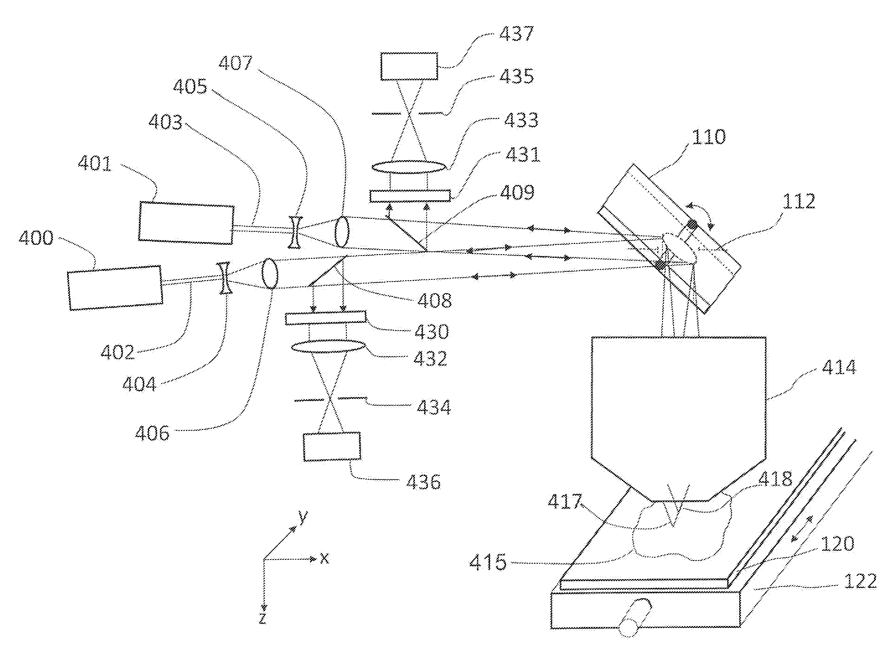
[0047]FIG. 4 shows a confocal scanning-beam / scanning-stage optical macroscope with two illumination / defection arms that is a first embodiment of this invention.

[0048]In this embodiment, a first incoming collimated laser beam 402 from laser 400 passes through a beam expander (comprised of lens 404 and lens 406), and is expanded to match the diameter of entrance pupil 112 of scan lens 414 (note—entrance pupil 112 as indicated on Figure simply indicates the position of the entrance pupil of scan lens 414. A real stop is not placed at this position). Scanning mirror 110 deflects the beam to move the scanning spot in the X direction. Scan lens 414 focuses the beam to spot 418 on specimen 415, mounted on microscope slide 120, and light reflected from or emitted by the specimen is collected by scan lens 414, descanned by scanning mirror 110, and partially reflected by beamsplitter 408 into a first confocal detection arm comprised of laser rejection filter 430, lens 432, pinhole 434, and de...

Example

[0063]Just as with the first embodiment, a major advantage of the second embodiment of this invention when scanning multiple fluorophores is that each fluorophore can be excited and detected separately, but detection is simultaneous instead of sequential, reducing the scan time considerably. This can be combined with the advantages of the prior art macroscope described earlier—the ability to predict the exposure required for each fluorophore using a high-speed preview scan, which allows the gain of the separate detectors to be adjusted for simultaneous defection of weak and strong fluorophores, and the ability to scan very large specimens.

[0064]The second embodiment of the present invention is a combination of two instruments sharing the same optical beam path, mirror scanner, scan lens and moving specimen stage, but different sources that illuminate different focus spots on the specimen, and separate detection arms for signals emitted from each focused spot. As before, the two inst...

Example

[0068]Although this disclosure of the third embodiment of this invention has described an Instrument with two discrete point light sources in the focal plane of lens 106, and a single detection arm containing two detectors, additional point light sources and detectors can be utilized.

[0069]Note that the ends of fiber optic cables 502 and 503 are placed at positions 506 and 505 in the focal plane of lens 106, such that the two fiber optic ends are in a line parallel to the Y axis. This results in the two focus spots 516 and 518 being positioned along a line parallel to the Y axis, and the pinholes 634 and 838 are also placed on a line parallel to the Y axis, and positioned to transmit light from focus spots 518 and 516 respectively towards detectors 636 and 640.

[0070]If light sources 500 and 501 have different frequencies chosen to match the excitation peak of two different fluorophores, for example), then beamsplitter 610 should be chosen to reflect a broad band of wavelengths that ...


PUM

PropertyMeasurementUnit
Diameteraaaaaaaaaa
Distanceaaaaaaaaaa
Wavelengthaaaaaaaaaa

Abstract

An instrument and method for scanning a large specimen supported on a specimen holder has a plurality of illumination sources with each illumination, source being focused on a different focus spot of the specimen simultaneously. There are a plurality of spectrally resolved detectors to receive light reflected or emitted from the different focus spots simultaneously with each spectrally resolved detector receiving light from one illumination source only.

Description

BACKGROUND OF THE INVENTION[0001]1. Field of the Invention[0002]This invention relates to the fields of confocal and non-confocal imaging of large microscope specimens with particular emphasis on scanning beam fluorescence and photoluminescence imaging systems, including multi-photon fluorescence, spectrally-resolved fluorescence, and second and third harmonic imaging. Applications include imaging tissue specimens, genetic microarrays, protein arrays, tissue arrays, cells and cell populations, biochips, arrays of biomolecules, detection of nanoparticles, photoluminescence imaging of semiconductor materials and devices, and many others.[0003]2. Description of the Prior Art[0004]FIG. 1 shows one embodiment of a prior art confocal scanning laser macroscope, as described in U.S. Pat. No. 5,760,951. In this embodiment, the incoming collimated laser beam 102 from laser 100 passes through a beam expander (comprised of lens 104 and lens 106), and is expanded to match the diameter of entranc...

Claims


Application Information

Patent Timeline
IPC IPC(8): G01N21/64
CPCG01N21/6452G01N2021/6421G01N2201/1042G01N2201/10G01N2021/6439
Inventor DAMASKINOS, SAVVASDIXON, ARTHUR EDWARD
Owner HURON TECH INT
Why Eureka
Try Eureka