
Liquid crystal heating device with communication function and control method

A technology of heating device and control method, applied in temperature control, control/regulation system, non-electric variable control and other directions, can solve the problem of low heating control accuracy, and achieve the effect of ensuring normal display and high heating control accuracy

Active Publication Date: 2019-01-22
CHONGQING HUAHONG INSTR
View PDF9 Cites 0 Cited by
  • Summary
  • Abstract
  • Description
  • Claims
  • Application Information

AI Technical Summary

Problems solved by technology

[0004] The purpose of the present invention is to overcome the disadvantage of low heating control precision of the heating module of the liquid crystal display in the prior art, and provide a liquid crystal heating device with communication function that has high heating control precision and effectively ensures the normal display of the liquid crystal display and control method

Method used


Image

  • Liquid crystal heating device with communication function and control method
  • Liquid crystal heating device with communication function and control method
  • Liquid crystal heating device with communication function and control method

Examples


Embodiment 1

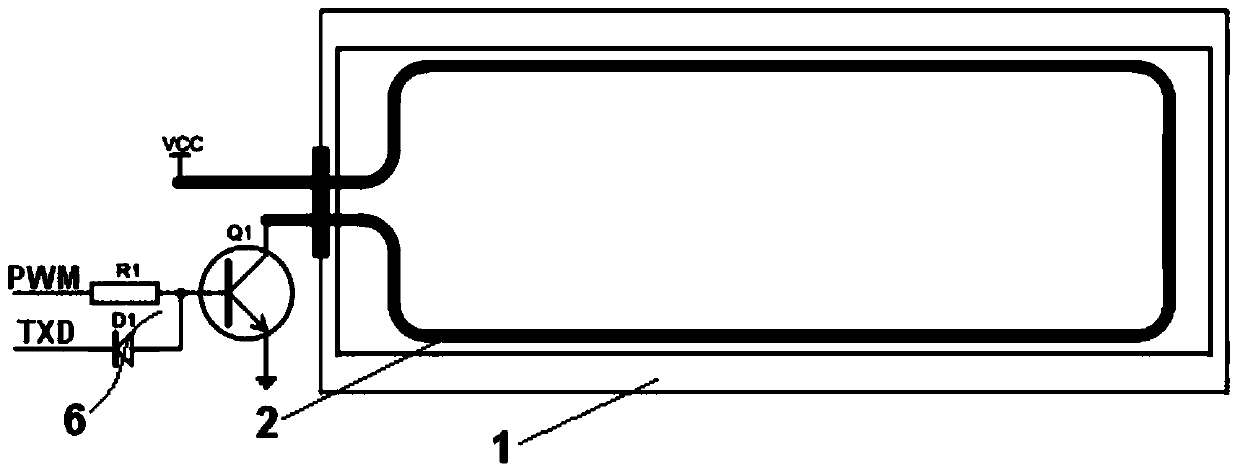
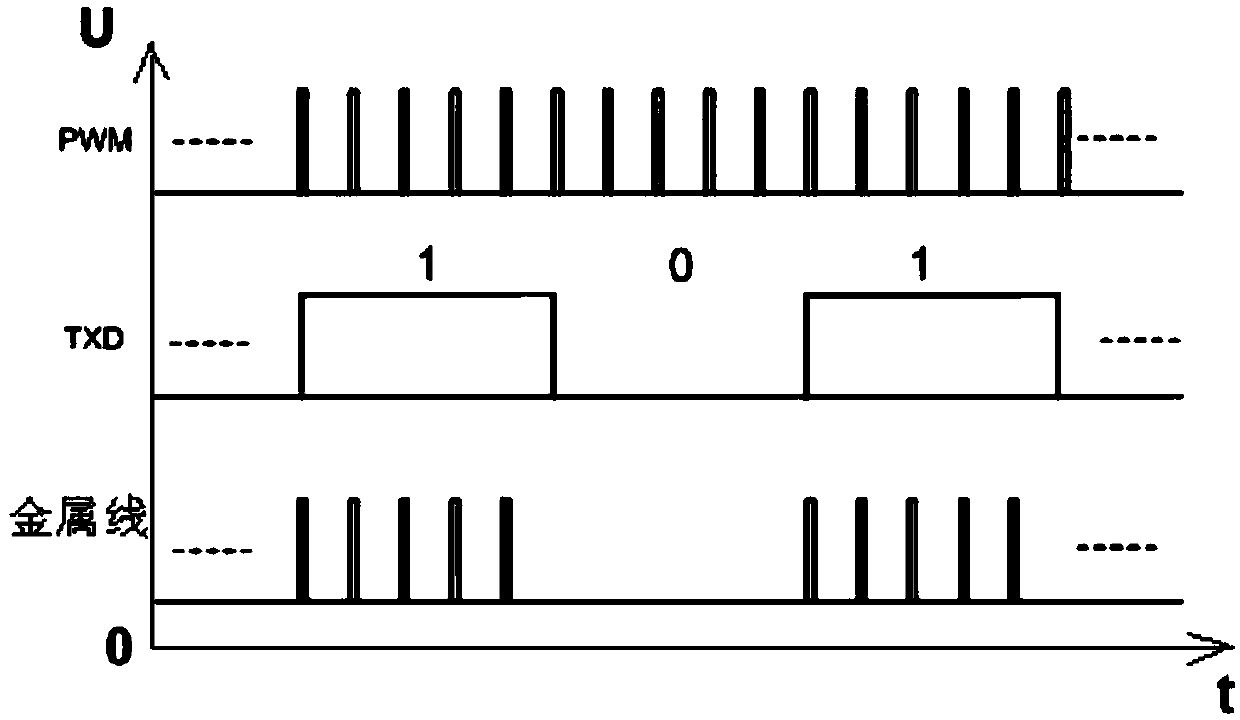
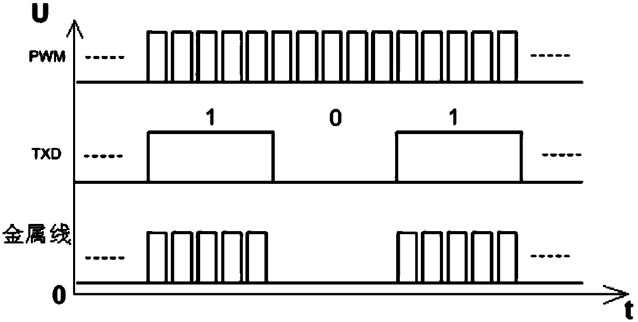
[0039] Such as figure 1 , Figure 4 The illustrated embodiment is a liquid crystal heating device with a communication function, comprising a metal wire 2 disposed on the inner surface of a liquid crystal display 1 of an electric energy meter, a single-chip microcomputer 3, a memory 4, a temperature sensor 5 and a temperature sensor disposed in the electric energy meter. Heating control circuit 6; the single-chip microcomputer is electrically connected with the memory and the temperature sensor respectively, and the metal wire is electrically connected with the VCC and the heating control circuit respectively, and the PWM switch signal output pin of the single-chip microcomputer and the metal wire heating control signal TXD pin are all connected with the heating control circuit. connect. The metal wire is made of metal electroplating layer, the metal wire extends along the edge of the liquid crystal display screen, and the metal wire is rectangular.

[0040] Such as figure ...

Embodiment 2

[0054] Embodiment 2 includes all structures and step parts of Embodiment 1, and Embodiment 2 also includes as Figure 4 The warning light 7 shown, the warning light is electrically connected with the single-chip electromechanical; Before the step 100 of embodiment 1, it also includes the temperature sensor failure detection step:

[0055] The standard temperature signal curve of the temperature sensor is set in the memory;

[0056] Step 90, the controller obtains the temperature signal curve S(t) of the temperature sensor, and the controller extracts the temperature signal value M corresponding to each time interval in S(t) 1 ,...,M n ;The serial number of the set temperature signal value is i, i=1,...,n;

[0057] Step 92, the controller utilizes the formula Calculate each temperature signal value M i The smooth rate ratio i ;

[0058] When S(t) has no intersection with the standard temperature signal curve and the ratio of each temperature signal value i If they are a...


PUM


Abstract

The invention discloses a liquid crystal heating device with a communication function and a control method. The liquid crystal heating device comprises a metal wire arranged on the inner surface of a liquid crystal display screen of an electric energy meter, as well as a single-chip microcomputer, a memory, a temperature sensor and a heating control circuit which are arranged in the electric energy meter, wherein the single-chip microcomputer is electrically connected with the memory and the temperature sensor; the metal wire is electrically connected with a VCC and the heating control circuit; and both a PWM (Pulse-Width Modulation) switch signal output pin and a metal wire heating control signal TXD pin of the single-chip microcomputer are electrically connected with the heating control circuit. The liquid crystal heating device has the characteristics that the heating control precision is high and normal display of the liquid crystal display screen is effectively ensured.

Description

technical field [0001] The invention relates to the technical field of liquid crystal display heating, in particular to a liquid crystal heating device with a communication function and a control method with high heating control precision and effective guarantee of normal display of the liquid crystal display. Background technique [0002] Liquid crystal displays are widely used due to their advantages of light weight, small size, and large effective display area. However, some parameters of liquid crystals change greatly under low temperature conditions, resulting in a decrease in the response speed of liquid crystals. At low temperatures (below -25°C), liquid crystals can't even work, and this weakness severely limits the application of liquid crystal displays. [0003] Chinese Patent Authorization Publication No.: CN101655621, the authorized publication date is February 24, 2010, which discloses a heating module for a liquid crystal display. The liquid crystal display inc...

Claims


Application Information

Patent Timeline
Patent Type & Authority Patents(China)
IPC IPC(8): G02F1/1333G05D23/20
CPCG02F1/133382G05D23/20
Inventor 钱海波何建英朱小玲牛延谋陈刚王剑波
Owner CHONGQING HUAHONG INSTR
Learn More