
A system and method for generating a pipeline routing diagram for a new subway station

A subway station and generation system technology, applied in the direction of instrumentation, geometric CAD, calculation, etc., can solve the problems of labor-consuming and time-consuming graphic cutting, high probability of error, and long time for modifying the design, etc., to achieve intuitive three-dimensional space position and reduce Effects of Design Errors and Burden Reduction

Inactive Publication Date: 2018-11-23
BEIJING JIAOTONG UNIV
View PDF4 Cites 0 Cited by
  • Summary
  • Abstract
  • Description
  • Claims
  • Application Information

AI Technical Summary

Problems solved by technology

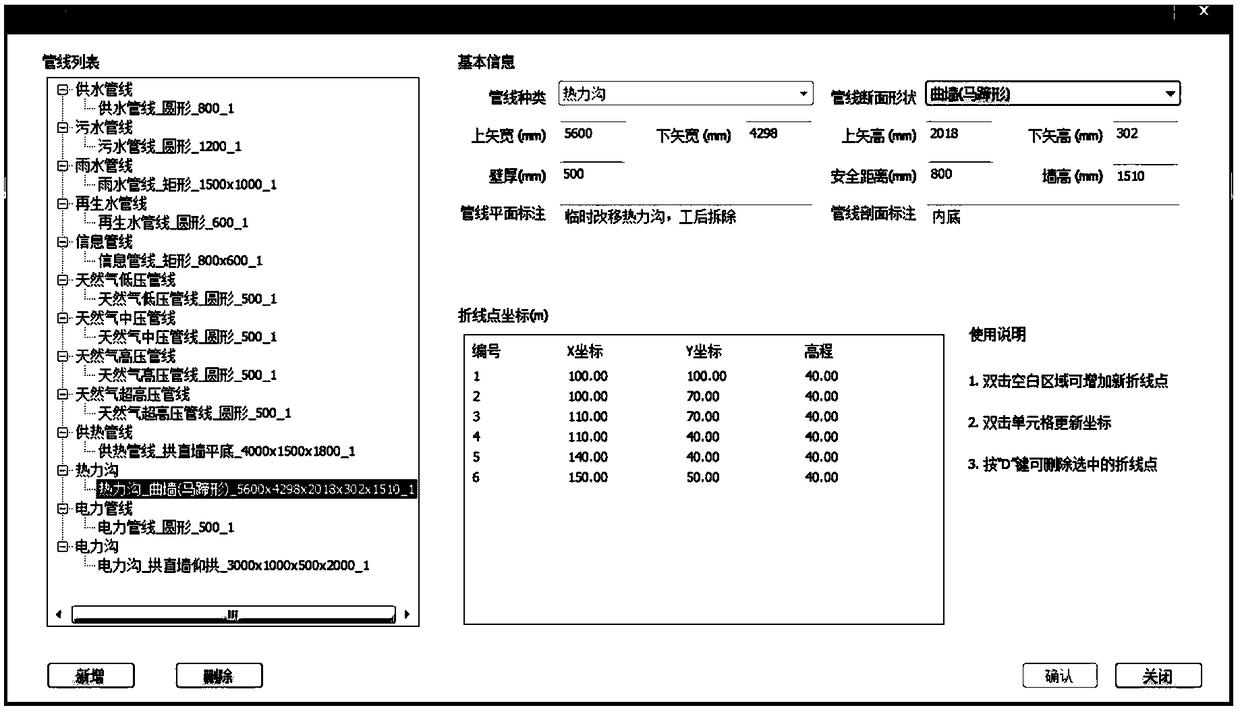
There are not only a large number of municipal pipelines, but also various types. In the special design of pipeline relocation and the demonstration of the relocation plan, there are the following problems: the time for the designer to do the special design of the relocation and the subsequent modification of the design are long; In the special design made by hand, the probability of error is high; in the special design made by hand, the graphic section is labor-intensive and time-consuming, so that the special design gives fewer cross-sections, which cannot fully reflect the three-dimensional space position of the pipeline; During the special design review of pipeline relocation, it is difficult to modify and demonstrate the modification suggestions put forward by the participants on the spot, which increases the difficulty of the review and reduces the efficiency of the review

Method used


Image

  • A system and method for generating a pipeline routing diagram for a new subway station
  • A system and method for generating a pipeline routing diagram for a new subway station
  • A system and method for generating a pipeline routing diagram for a new subway station

Examples


Embodiment Construction

[0036] In order to illustrate the present invention more clearly, the present invention will be further described below in conjunction with preferred embodiments and accompanying drawings. Similar parts in the figures are denoted by the same reference numerals. Those skilled in the art should understand that the content specifically described below is illustrative rather than restrictive, and should not limit the protection scope of the present invention.

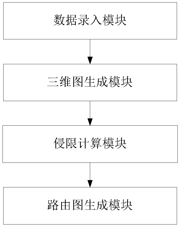
[0037] Such as figure 1 and figure 2 As shown, the calling method of the pipeline routing diagram generation system of the new subway station built on the CAD system platform provided by this embodiment is to load the PIPELINECAD application through the APPLOAD command in AutoCAD, and PIPELINECAD is the CAD system provided by this embodiment. The name of the pipeline routing diagram generation system of the new subway station on the platform in the CAD system platform, the system includes:

[0038] The data input module...


PUM


Abstract

The invention discloses a pipeline routing map generating system and a pipeline routing map generating method for a newly-built subway station. The system is established on a CAD (Computer Aided Design) system platform, and comprises a data input module, a three-dimensional map generating module, an intrusion limit calculating module and a routing map generating module, wherein the data input module is used for inputting pipeline data of the newly-built subway station and obstructing volume data and pipeline data of existing pipelines; the three-dimensional map generating module is used for generating an initial three-dimensional map according to the input data; the intrusion limit calculating module is used for calculating intrusion limit according to the initial three-dimensional map, and respectively marking an intrusion limit part on each of pipelines of the newly-built subway station and the existing pipelines to obtain a three-dimensional map with intrusion limit marks; the routing map generating module is used for generating a pipeline routing map by adopting the principle that the total length of the pipelines is the minimal on the basis that the clearances of the pipelines and obstructing bodies of the newly-built subway station do not intrude on the clearances of the existing pipelines based on the three-dimensional map with the intrusion marks according to a starting point and a terminal point of a pipeline route input by a user. According to the system and the method, the burden of a designer is lightened, the design work efficiency is improved, and design errors are reduced.

Description

technical field [0001] The invention relates to the technical field of municipal engineering. More specifically, it relates to a system and method for generating a pipeline routing diagram of a newly built subway station. Background technique [0002] Urban rail transit projects are mainly built in bustling urban areas, which are inevitably adjacent to or crossing a large number of municipal pipelines. At the same time, new stations will add a certain number of pipelines. The pipelines involved in each subway station range from a dozen to as many as hundreds. There are not only a large number of municipal pipelines, but also various types. In the special design of pipeline relocation and the demonstration of the relocation plan, there are the following problems: the time for the designer to do the special design of the relocation and the subsequent modification of the design are long; In the special design made by hand, the probability of error is high; in the special desi...

Claims


Application Information

Patent Timeline
Patent Type & Authority Patents(China)
IPC IPC(8): G06F17/50
CPCG06F30/18G06F2113/14
Inventor 杨成永谷长海马文辉程霖
Owner BEIJING JIAOTONG UNIV
Learn More