Electric fish stabbing casting pole
An electric, fish stabbing technique applied to throwing rods. It can solve problems such as easy to run fish, not enough depth and not firm enough, and achieve the effect of reducing labor intensity
- Summary
- Abstract
- Description
- Claims
- Application Information
AI Technical Summary
Problems solved by technology
Method used
Image

Examples
Embodiment 1
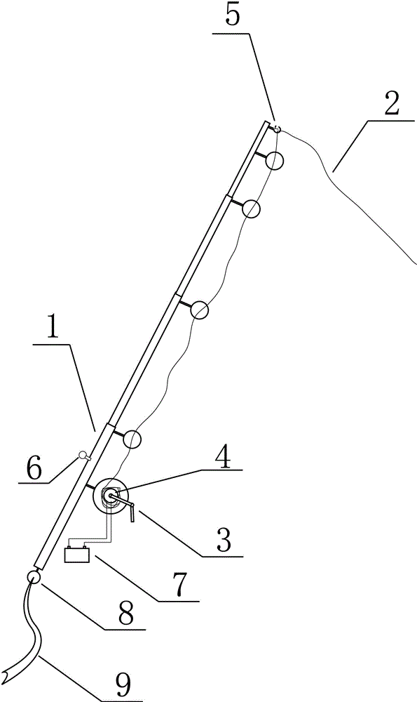
[0022] Embodiment 1: An electric stickleback throwing rod consists of a fishing rod (1), a fishing line (2), an electric reel (3), a motor (4), a pull switch (5), an alarm (6), Battery (7), fixed rope ring (8), fixed rope (9), described electric reel (3), pull switch (5), alarm (6), fixed rope ring (8) are fixed on On the fishing rod (1), the battery (7) is connected to the electric reel (3) and the motor (4), the pull switch (5) is installed on the front end of the fishing rod (1), and the pulling The small hook of the switch (5) is a ring that can be quickly opened and closed. Pull the switch (5) to protrude from the small hook. The fishing line (2) is wound on the electric reel (3), and the front end of the fishing line (2) is placed on the pull On the small hook protruding from the switch (5), the fixed rope ring (8) is installed on the fishing rod (1) and connected with the fixed rope (9), and the described alarm (6) is a sounding and light-emitting horn .
[0023] A ki...
Embodiment 2
[0030] Embodiment 2: An electric stickleback throwing rod consists of a fishing rod (1), a fishing line (2), an electric reel (3), a motor (4), a pull switch (5), an alarm (6), Battery (7), fixed rope ring (8), fixed rope (9), described electric reel (3), pull switch (5), alarm (6), fixed rope ring (8) are fixed on On the fishing rod (1), the battery (7) is connected to the electric reel (3) and the motor (4), the pull switch (5) is installed on the front end of the fishing rod (1), and the pulling The small hook of the switch (5) is a ring that can be quickly opened and closed. Pull the switch (5) to protrude from the small hook. The fishing line (2) is wound on the electric reel (3), and the front end of the fishing line (2) is placed on the pull On the small hook protruding from the switch (5), the fixed rope ring (8) is installed on the fishing rod (1) and connected with the fixed rope (9), and the described alarm (6) is a sounding and light-emitting horn .
[0031] A ki...
Embodiment 3
[0038] Embodiment 3: An electric stickleback throwing rod consists of a fishing rod (1), a fishing line (2), an electric reel (3), a motor (4), a pull switch (5), an alarm (6), Battery (7), fixed rope ring (8), fixed rope (9), described electric reel (3), pull switch (5), alarm (6), fixed rope ring (8) are fixed on On the fishing rod (1), the battery (7) is connected to the electric reel (3) and the motor (4), the pull switch (5) is installed on the front end of the fishing rod (1), and the pulling The small hook of the switch (5) is a ring that can be quickly opened and closed. Pull the switch (5) to protrude from the small hook. The fishing line (2) is wound on the electric reel (3), and the front end of the fishing line (2) is placed on the pull On the small hook protruding from the switch (5), the fixed rope ring (8) is installed on the fishing rod (1) and connected with the fixed rope (9), and the described alarm (6) is a sounding and light-emitting horn , the battery (7...
PUM
 Abstract
Description
Claims
Application Information
 - R&D
- Intellectual Property
- Life Sciences
- Materials
- Tech Scout
- Unparalleled Data Quality
- Higher Quality Content
- 60% Fewer Hallucinations
Browse by: Latest US Patents, China's latest patents, Technical Efficacy Thesaurus, Application Domain, Technology Topic, Popular Technical Reports.
© 2025 PatSnap. All rights reserved.Legal|Privacy policy|Modern Slavery Act Transparency Statement|Sitemap|About US| Contact US: help@patsnap.com