Method for removing steel tube blank tip

A technology of steel pipe and billet end, which is applied in the field of cutting equipment to achieve the effects of slowing impact, improving stability, and improving blanking stability

Active Publication Date: 2016-07-20
宝武特冶航研科技有限公司
View PDF8 Cites 10 Cited by
  • Summary
  • Abstract
  • Description
  • Claims
  • Application Information

AI Technical Summary

Problems solved by technology

[0005] Aiming at the deficiencies of the above-mentioned prior art, the technical problem to be solved by the present invention is: how to provide a method for removing the end of the steel pipe billet that can well remove the burr of the incision, improve the cutting quality, improve the cutting efficiency, reduce pollution, and have low cost

Method used


Image

  • Method for removing steel tube blank tip
  • Method for removing steel tube blank tip

Examples


Embodiment Construction

[0037] The present invention will be further described in detail below in conjunction with the accompanying drawings.

[0038] During the specific implementation: a method for removing the end of a steel pipe billet, which is characterized in that the cutting of the end of the steel pipe is realized by water cutting, and the burr generated at the cutting part is removed by using the deformation dispersion of the cutting water flow itself during water cutting wash off.

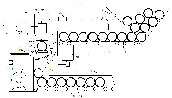
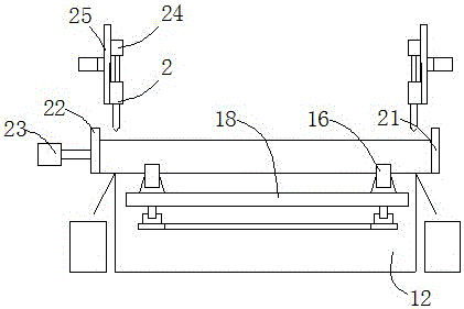
[0039] Specifically, when this method is implemented, the figure 1 and figure 2 A steel pipe end cutting machine shown is realized. The steel pipe end cutting machine includes a frame 1, a feeding part structure, a cutting part structure and a discharging part structure that are installed on the frame 1 and connected in sequence, wherein, The cutting part structure includes a steel pipe positioning device for positioning the steel pipe to be cut and two steel pipe end cutting devices. One side of the steel p...


PUM

PropertyMeasurementUnit
diameteraaaaaaaaaa

Abstract

The invention discloses a method for removing a steel tube blank tip. The method is characterized in that the steel tube tip is cut in a water cutting manner, and burrs generated on the cut part are washed away through the deformation dispersity of cutting water flow itself during water cutting. The method has the beneficial effects that implementation is easy, the burrs on a notch can be well removed, the cutting quality is improved, the cutting efficiency is improved, pollution is reduced, and cost is low.

Description

technical field [0001] The invention relates to cutting equipment for finished steel pipes and ends of pipe blanks, in particular to a method for removing the ends of steel pipe blanks by applying the principle of water cutting to cutting steel pipes. Background technique [0002] The manufacturing process of the steel pipe is complicated. After the general steel pipe is manufactured, it is usually a steel pipe billet. The two ends of the steel pipe billet are usually relatively rough. Further, a series of head cutting, tail cutting or cutting according to the required length is carried out on the steel pipe billet. To make the steel pipe meet the accurate length requirements and the end to be flat and smooth to facilitate the next process, especially the finished pipe has higher requirements on the cutting quality of the end. [0003] In the prior art, the lengthy steel pipes are generally cut to the required length by cutting or sawing with a grinding wheel cutting machin...

Claims


Application Information

Patent Timeline
Patent Type & Authority Applications(China)
IPC IPC(8): B23D79/00B23Q7/14B23Q7/10B23Q3/18
CPCB23D79/00B23Q3/18B23Q7/10B23Q7/1447B23Q2240/007
Inventor 吴建军陈沈云肖都跃
Owner 宝武特冶航研科技有限公司
Why Eureka
Try Eureka