Automatic centering hydraulic fixture

A technology of hydraulic fixtures and fixtures, which is applied in the direction of clamping, manufacturing tools, supports, etc., can solve the problems of uneven distribution of cylinder blank machining allowance, unreasonable allocation of cylinder blank machining allowance, and increase of processing procedures, etc., to achieve Ensure normal production operation and solve the effect of uneven distribution of machining allowance

Inactive Publication Date: 2016-07-20
ANHUI HUALING AUTOMOBILE
View PDF7 Cites 3 Cited by
  • Summary
  • Abstract
  • Description
  • Claims
  • Application Information

AI Technical Summary

Problems solved by technology

[0006] However, because ordinary automatic hydraulic fixtures only position the outer surface of the cylinder blank, when there is an error in the manufacture of the outer surface of the cylinder blank, it is easy to cause inaccurate positioning in other places, so that the fixture blank is far from the position that needs to be positioned theoretically. Large, the distribution of the machining allowance of the cylinder blank is not uniform enough, so that the final processed product state is not the best device, and at the same time, there is a higher requirement for the casting size of the cylinder blank, resulting in more waste of the cylinder blank
[0007] The shape positioning adopted by ordinary automatic hydraulic clamps can make the partial parts of the cylinder block blanks placed in ideal positions, but for the entire cylinder block blanks, the cumulative error is large, which is not the most ideal position, and the cylinder block blanks cannot be reasonably allocated In the process of processing, it is often necessary to increase the processing steps and adjust the state of the workpiece many times, wasting time

Method used


Image

  • Automatic centering hydraulic fixture
  • Automatic centering hydraulic fixture
  • Automatic centering hydraulic fixture

Examples


Embodiment Construction

[0033] The core of the present invention is to provide an automatic centering hydraulic fixture, which can position and clamp the cylinder blank by adding a centering mechanism, and the positioning accuracy is significantly improved.

[0034] In order to enable those skilled in the art to better understand the solution of the present invention, the present invention will be further described in detail below in conjunction with the accompanying drawings and specific embodiments.

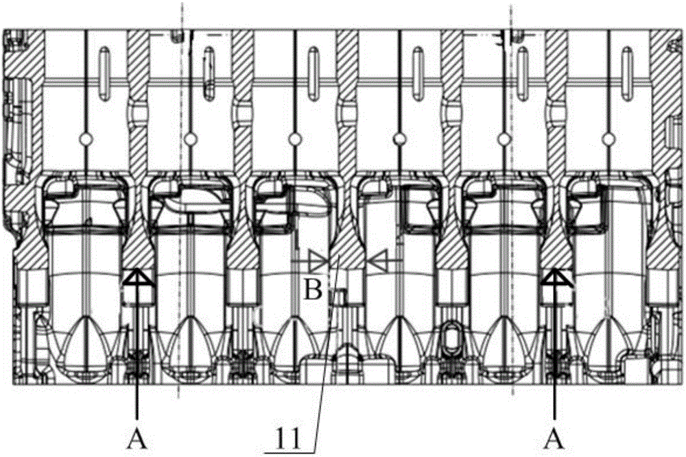
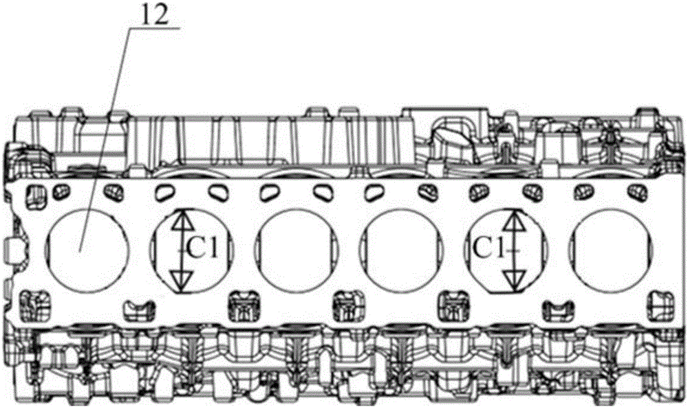
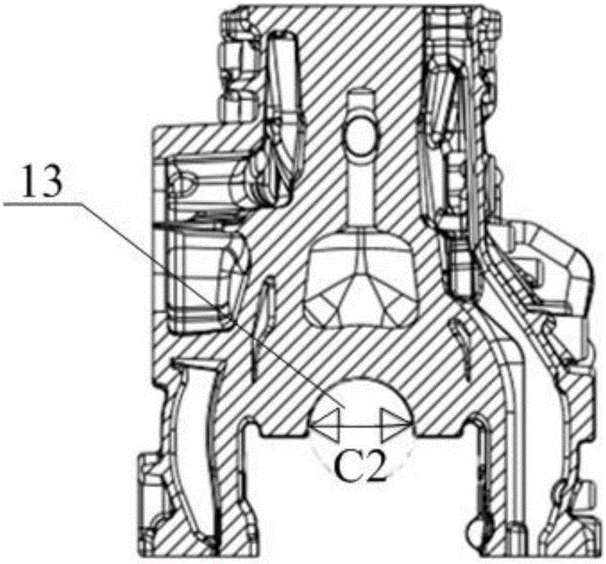
[0035] Please refer to Figure 1 to Figure 7 , figure 1 It is the front view of the cylinder blank in the prior art; figure 2 It is a top view of the cylinder blank in the prior art; image 3 It is the left view of the cylinder blank in the prior art; Figure 4 It is a structural schematic diagram of a specific embodiment of the automatic centering hydraulic clamp provided by the present invention; Figure 5 for Figure 4 Schematic diagram of the structure of the left and right central position...


PUM


Abstract

The invention discloses an automatic centering hydraulic fixture. The automatic centering hydraulic fixture comprises a fixture body, a stand column mounted on the fixture body for penetrating through a cylinder hole of a cylinder blank, height positioning parts mounted on the two sides of the fixture body and used for supporting the cylinder blank, a left-right centering positioning part mounted at the middle part of the fixture body and used for positioning in the thickness direction of a main bearing base of the cylinder blank, and a first front-back centering positioning part mounted on the stand column and used for positioning in the front-back diameter direction of the cylinder hole. The automatic centering hydraulic fixture, provided by the invention, respectively positions the height direction, the left-right direction and the front-back direction of the cylinder blank, realizes three-dimensional positioning of the cylinder blank, provides excellent positioning foundation for subsequent further clamping and machining procedures, can effectively solve the problem of nonuniform machining allowance distribution of the cylinder blank, guarantees high-efficiency and high-quality positioning and clamping of the cylinder blank, and guarantees normal production of a quick production line.

Description

technical field [0001] The invention relates to the field of mechanical processing equipment, in particular to an automatic centering hydraulic clamp. Background technique [0002] Before the cylinder blank is processed, the cylinder blank needs to be positioned and clamped, such as Figures 1 to 3 As shown, the cylinder block blank is composed of a number of main bearing seats arranged, with a number of cylinder holes running through the top surface, and a semicircular hole is opened in the lower part of the main bearing seat. [0003] In the prior art, most of the jigs used to clamp the cylinder blank are manual adjustment fixtures. After the cylinder blank needs to be marked manually, it is then installed on the fixture for processing. During the process, the workpiece needs to be adjusted again in the fixture. position on the [0004] For the manual adjustment fixture, through the form of scribing, the state of the cylinder blank on the fixture can be adjusted many time...

Claims


Application Information

Patent Timeline
Patent Type & Authority Applications(China)
IPC IPC(8): B23Q3/08
CPCB23Q3/082
Inventor 王标汪祥支梁加刚李浩黄新宇刘琳琳陶文康韩伟
Owner ANHUI HUALING AUTOMOBILE
Why Eureka
Try Eureka