The spindle of the machining center does not stop rotating, and there is an automatic tool changer for manipulators

A machining center and automatic tool change technology, applied in metal processing machinery parts, positioning devices, metal processing equipment, etc., can solve the problem of time waste, reduce production costs, have broad application prospects, and save tool change time.

Active Publication Date: 2018-02-06
NANTONG OUKE CNC EQUIP CO LTD
View PDF6 Cites 0 Cited by
  • Summary
  • Abstract
  • Description
  • Claims
  • Application Information

AI Technical Summary

Problems solved by technology

The tool change of the machine tool is usually carried out after the spindle stops rotating, but it takes a certain amount of time from the stop of the machine tool spindle to the restart to reach the rated speed, which is actually a waste of time. The auxiliary time required for the rated speed, the present invention provides an automatic tool changer with a manipulator for the spindle of the machining center that does not stop rotating, aiming at reducing the auxiliary time for processing and improving the utilization rate of the machine tool

Method used


Image

  • The spindle of the machining center does not stop rotating, and there is an automatic tool changer for manipulators
  • The spindle of the machining center does not stop rotating, and there is an automatic tool changer for manipulators
  • The spindle of the machining center does not stop rotating, and there is an automatic tool changer for manipulators

Examples


Embodiment Construction

[0042] The automatic tool changer with manipulator for non-stop rotation of the spindle of the machining center proposed by the present invention will be further described in detail below in conjunction with the accompanying drawings and specific embodiments. Advantages and features of the present invention will be apparent from the following description and claims. It should be noted that the drawings are all in very simplified form and use imprecise ratios, which are only used to facilitate and clearly assist the purpose of illustrating the embodiments of the present invention.

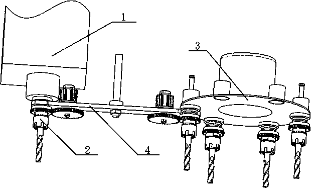
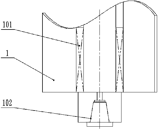
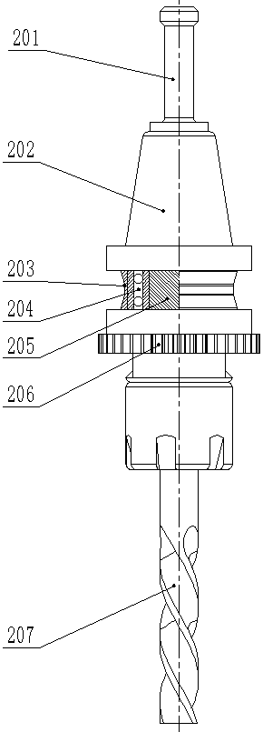
[0043]The spindle of the machining center rotates continuously and has an automatic tool changing device with a manipulator, which is characterized in that it includes a main shaft 1, a tool handle 2, a tool magazine 3, a tool changing manipulator 4 and a numerical control system (not shown).

[0044] The main shaft 1 includes an electric main shaft rotation driving device 101 in the middle, an inne...


PUM


Abstract

The invention belongs to the field of numerical control machining devices and specifically relates to an automatic tool changer (ATC) with a manipulator and an incessantly rotating spindle for a machining center. The ATC comprises the spindle, tool handles, a tool magazine, the tool changing manipulator and a numerical control system. The spindle has the functions of speed governing and circumferential position real-time detection and adjusting. Each tool handle comprises an outer conical handle body coaxially connected with the spindle, a tool body, a bearing arranged on the tool body in a sleeving mode, a groove, a meshing device A and a tool. The tool magazine comprises a plurality of tool positions and a tool position changing device. Each tool position comprises a conical sleeve used for clamping the corresponding tool, tool driving motors, a tool circumferential position real-time detection and adjusting system, and a meshing device B meshing with the corresponding tool. The tool driving motors drive the tools to rotate. Through the ATC, fast tool changing can be achieved between a tool on the spindle of the machining center and the tools in the tool magazine under the circumstance that the spindle rotates incessantly, so that the auxiliary machining time during machining of the machining center is saved, the service efficiency of a numerically-controlled machine tool is improved, the machining cost is reduced, and the application prospects are wide.

Description

technical field [0001] The invention belongs to the field of numerical control machining devices, in particular to a fast automatic tool changing device for a spindle of a numerical control machining center without stopping rotation. Background technique [0002] The development and application of electric spindles, high-speed lead screws and linear motors have greatly improved cutting efficiency. In order to match the high efficiency of machine tools, the high-speed automatic tool changer (ATC), one of the important components of machining centers, has also become a high-speed machining tool. Important technical content of the center. With the improvement of cutting speed and the continuous shortening of cutting time, the requirements for tool change time are also gradually increasing. The speed of tool change has become an important indicator of high-level machining centers. [0003] There are three main methods to measure tool change speed: 1. Tool-to-tool tool change ti...

Claims


Application Information

Patent Timeline
Patent Type & Authority Patents(China)
IPC IPC(8): B23Q3/155
CPCB23Q3/15506
Inventor 殷振张磊汪帮富钱蜜齐芳娟伯洁杨鑫铭刘嵚昀黄开明吴雷
Owner NANTONG OUKE CNC EQUIP CO LTD
Why Eureka
Try Eureka