Bionic grabbing manipulator

A technology for grasping manipulators and manipulators, applied in the direction of manipulators, chucks, manufacturing tools, etc., can solve the problems of high control difficulty and inability to adapt to grasping of various objects, and achieve simple transmission structure, reduce control difficulty, and transmission precise effect

Active Publication Date: 2016-07-20
KUNMING UNIV OF SCI & TECH
View PDF10 Cites 4 Cited by
  • Summary
  • Abstract
  • Description
  • Claims
  • Application Information

AI Technical Summary

Problems solved by technology

[0003] The invention provides a bionic grasping manipulator, which is used to solve the problem that the traditional manipulator is difficult to control and cannot adapt to grasping of various objects

Method used


Image

  • Bionic grabbing manipulator
  • Bionic grabbing manipulator
  • Bionic grabbing manipulator

Examples


Embodiment 1

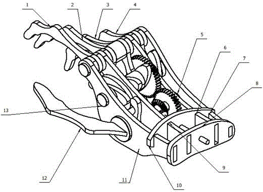
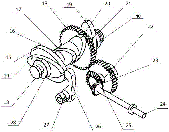
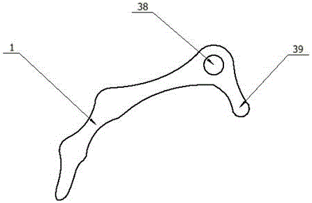
[0020] Embodiment 1: as Figure 1-8 As shown, a bionic grasping manipulator includes manipulator index finger 1, manipulator middle finger 2, manipulator ring finger 3, manipulator little finger 4, gear shaft I5, palm support plate III6, palm support plate IV7, outer support frame 8, palm support plate II9 , Inner support frame 10, palm support plate Ⅰ11, manipulator thumb 12, gear shaft Ⅱ13, index finger control cam 14, thumb control cam 15, limit block Ⅰ16, middle finger control cam 17, large cylindrical gear 18, little finger control cam 19, ring finger Control cam 20, limit block II 21, small cylindrical gear 22, large bevel gear 23, input shaft 24, small bevel gear 25, swing rod 26, limit block III 27, limit block IV 28, finger fixing shaft 29, palm support plate Ⅳ installation position 30, little finger installation position 31, palm support plate Ⅲ installation position 32, ring finger installation position 33, middle finger installation position 34, palm support plate ...

Embodiment 2

[0023] Embodiment 2: as Figure 1-8 As shown, a bionic grasping manipulator includes manipulator index finger 1, manipulator middle finger 2, manipulator ring finger 3, manipulator little finger 4, gear shaft I5, palm support plate III6, palm support plate IV7, outer support frame 8, palm support plate II9 , Inner support frame 10, palm support plate Ⅰ11, manipulator thumb 12, gear shaft Ⅱ13, index finger control cam 14, thumb control cam 15, limit block Ⅰ16, middle finger control cam 17, large cylindrical gear 18, little finger control cam 19, ring finger Control cam 20, limit block II 21, small cylindrical gear 22, large bevel gear 23, input shaft 24, small bevel gear 25, swing rod 26, limit block III 27, limit block IV 28, finger fixing shaft 29, palm support plate Ⅳ installation position 30, little finger installation position 31, palm support plate Ⅲ installation position 32, ring finger installation position 33, middle finger installation position 34, palm support plate ...


PUM


Abstract

The invention relates to a bionic grabbing manipulator, belonging to the technical field of robot operation. The bionic grabbing manipulator comprises a manipulator index finger, a manipulator middle finger, a manipulator ring finger, a manipulator little finger, a gear shaft I, a palm supporting plate III, a palm supporting plate IV, an outer side supporting rack, a palm supporting plate II, an inner side supporting rack, a palm supporting plate I, a manipulator thumb, a gear shaft II, an index finger control cam, a thumb control cam, a limiting block I, a middle finger control cam, a large cylindrical gear, a little finger control cam, a ring finger control cam, a limiting block II, a small cylindrical gear, a large bevel gear, an input shaft, a small bevel gear, an oscillating bar, a limiting block III, a limiting block IV, a finger fixing shaft, a palm supporting plate IV assembly position, a little finger assembly position, a palm supporting plate III assembly position, a ring finger assembly position, a middle finger assembly position, a palm supporting plate I assembly position, an index finger assembly position, a palm supporting plate II assembly position, a through hole, a positioning rod and a limiting block V. By adopting the bionic grabbing manipulator, the grabbing efficiency can be improved, and the control difficulty can be reduced.

Description

technical field [0001] The invention relates to a bionic grasping manipulator, which belongs to the technical field of robot operation. Background technique [0002] As we all know, a manipulator is a mechanical device, shaped like a hand, that can imitate certain movements and functions of a human arm, and is an automatic operating device for fixing programs to grab, carry objects or operate tools. The manipulator is the earliest industrial robot and the first modern robot. It can replace the heavy labor of people to realize the mechanization and automation of production, and can operate in harmful environments to protect personal safety. Therefore, it is widely used in bionic robots. Usually, the manipulator of a bionic robot is specific, and it is only designed for a specific operation object. It cannot be used without a specific target, and cannot be used as a highly bionic component such as a robot hand. Contents of the invention [0003] The invention provides a bio...

Claims


Application Information

Patent Timeline
IPC IPC(8): B25J15/08B25J15/10
CPCB25J15/086B25J15/103
Inventor 王梦盈吴海涛刘泓滨
Owner KUNMING UNIV OF SCI & TECH
Why Eureka
Try Eureka