Rear torsion beam structure of automobile

A technology for torsion beams and automobiles, which is applied to vehicle components, interconnection systems, suspensions, etc., can solve the problems of large occupied space and complicated platform design, and achieve the effect of reducing occupied space, reducing adjustment difficulty and convenient layout.

Active Publication Date: 2016-07-20
CHERY AUTOMOBILE CO LTD
View PDF6 Cites 3 Cited by
  • Summary
  • Abstract
  • Description
  • Claims
  • Application Information

AI Technical Summary

Problems solved by technology

[0003] At present, the cross-beam of the rear torsion beam structure mainly adopts a V-shaped or square cross-section structure, which takes up a lot of space, and often needs to add torsion bar springs to adjust the torsional stiffness in platform-based applications, which undoubtedly complicates the platform-based design of products

Method used


Image

  • Rear torsion beam structure of automobile
  • Rear torsion beam structure of automobile
  • Rear torsion beam structure of automobile

Examples


Embodiment Construction

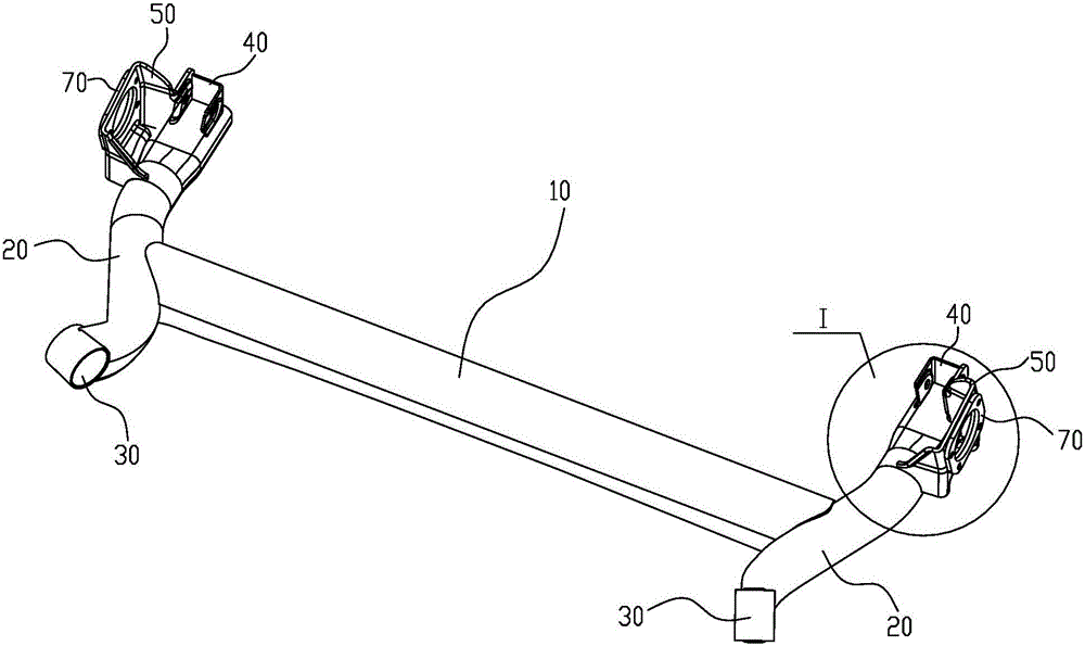
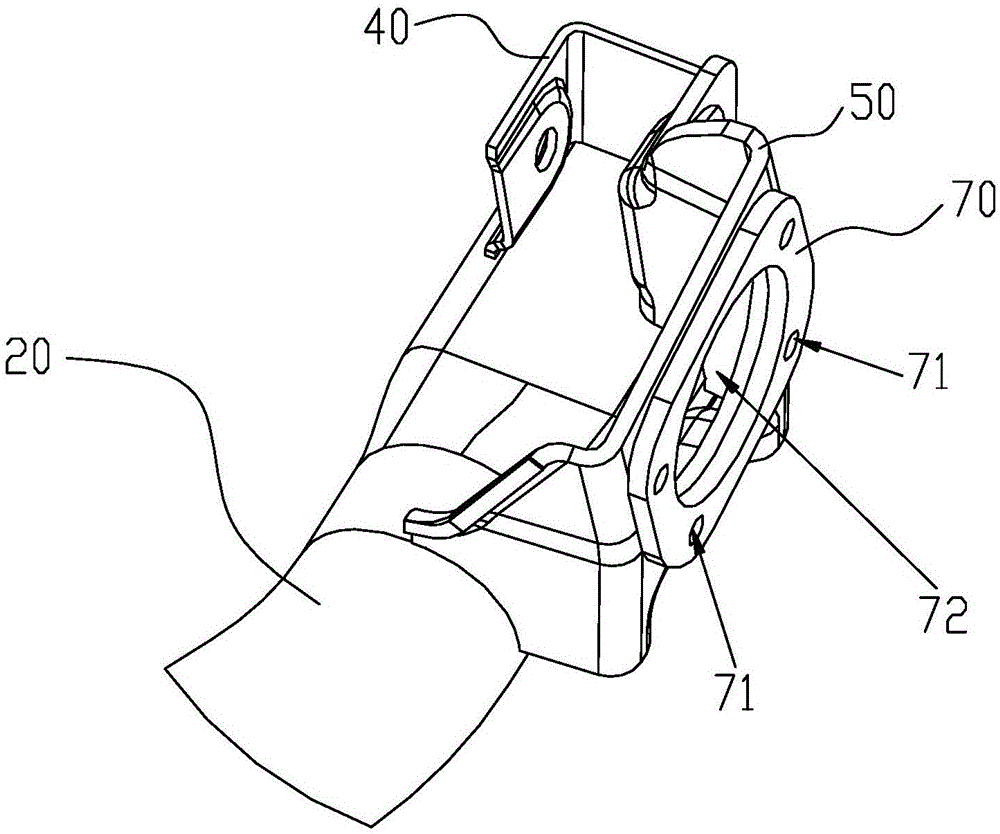
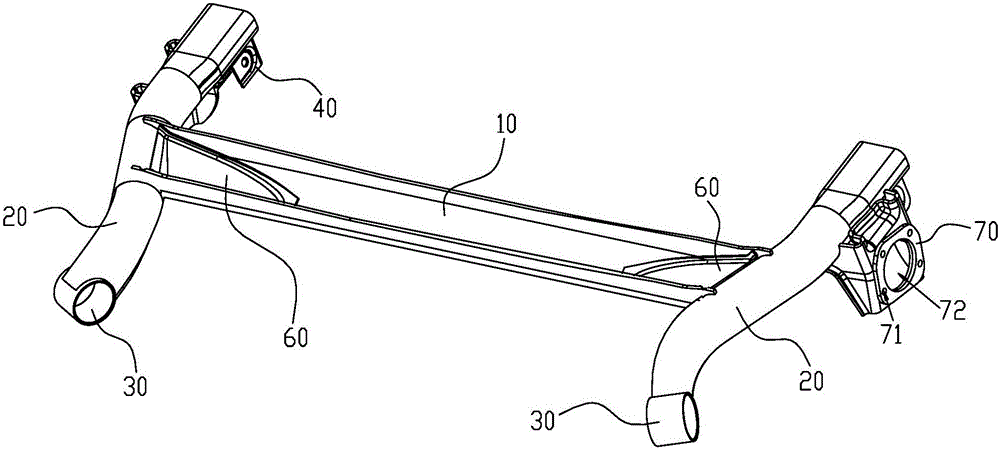
[0012] A car rear torsion beam structure, such as Figure 1-3 As shown, the crossbeam 10 is included, the two ends of the crossbeam 10 are respectively provided with a longitudinal beam 20, one end of the longitudinal beam 20 is provided with a bush sleeve 30, and the other end is provided with a shock absorber bracket 40, the beam body of the longitudinal beam 20 is close to the shock absorber A hub bracket 50 is provided at the position of the shock bracket 40 , and the cross-section of the beam 10 is U-shaped with the opening facing downward, and the cross-sectional area of ​​the beam 10 gradually increases symmetrically from the middle to both ends. The beam 10 with a U-shaped transverse section is selected, so that the torsional stress of the beam 10 can be dispersed, and the difficulty of adjusting the torsional stiffness is greatly reduced, which is not only beneficial to product development and design, but also ensures that the torsional stiffness and shear center posit...


PUM


Abstract

The invention discloses a rear torsion beam structure of an automobile. The rear torsion beam structure comprises a transverse beam, wherein longitudinal beams are respectively arranged at two ends of the transverse beam; a lining sleeve is arranged at one end of each longitudinal beam; a shock absorber bracket is arranged at the other end of each longitudinal beam; hub brackets are arranged at the positions close to the shock absorber brackets on the bodies of the longitudinal beams; the transverse sectional surface of the transverse beam takes the shape of an inverted U; the cross section area of the transverse beam is gradually increased from the middle to two ends in a symmetric manner. Due to the adoption of the transverse beam of which the transverse sectional surface is U-shaped, torsion stress can be dispersed, the adjusting difficulty of torsion rigidity can be greatly reduced, and thus development and design of products can be facilitated; meanwhile, as the torsion stress of the transverse beam is mainly concentrated at two ends, and the middle of the transverse beam is relatively slightly stressed, both the requirement on the torsion rigidity of the transverse beam can be ensured and the space occupied by the transverse beam can be effectively reduced due to adoption of a variable cross section structure which has a small middle and large two ends of the transverse beam, and thus other automobile parts around the transverse beam fittings can be arranged conveniently.

Description

technical field [0001] The invention belongs to the technical field of automobiles, and in particular relates to an automobile rear torsion beam structure. Background technique [0002] The rear torsion beam structure is the connecting force transmission device between the body and the wheels, which has an important impact on the safety, comfort and handling of the vehicle. At present, the commonly used rear torsion beam structure of automobile mainly includes a crossbeam, and the two ends of the crossbeam are respectively connected with longitudinal beams. On the beam body of the longitudinal beam, near the position of the shock absorber bracket, there are relatively spring seats for supporting the elastic element and hub brackets for installing the hub, where the hub bracket is located on the longitudinal beam away from the cross beam Surface arrangement, the rear torsion beam structure not only supports and installs corresponding automobile components, but also plays a r...

Claims


Application Information

Patent Timeline
Patent Type & Authority Applications(China)
IPC IPC(8): B60G21/055
CPCB60G21/055
Inventor 杨展张国忠孙义杰宋东奇黄震周浩泽毕如俊王超
Owner CHERY AUTOMOBILE CO LTD
Why Eureka
Try Eureka