Automatic grabbing machine convenient to move

An automatic and convenient technology, applied in the direction of conveyor objects, transportation and packaging, etc., can solve the problems of poor adaptability, large loss, inconvenient moving position, etc., to achieve convenient and flexible use, firm and reliable grasping, and diversified use range Effect

Inactive Publication Date: 2016-07-20
CHENGDU BEISEN WEIREN TECH CO LTD
View PDF5 Cites 6 Cited by
  • Summary
  • Abstract
  • Description
  • Claims
  • Application Information

AI Technical Summary

Problems solved by technology

Traditional industrial machine processing uses a fixed processing trajectory, which has poor adaptability. Due to changes in environmental parameters, such as equipment failures, accumulated movement errors, tool wear, solder changes, and subtle changes in part materials, even if the robot repeats the movements accurately, it is still impossible to avoid waste products. For the processing of high-value workpieces, once there is waste, the loss will be huge
Moreover, the existing grabbing device can only grab a single type of parts. Once the size of the parts changes, it will not be able to grab the parts firmly and reliably and ensure the safety of the parts. At this time, only by replacing the grab Device to achieve, poor adaptability
In addition, the existing grabbing devices are relatively heavy, and it is very inconvenient to move the position. At the same time, when grabbing small parts, it is always easy to grab empty.

Method used


Image

  • Automatic grabbing machine convenient to move
  • Automatic grabbing machine convenient to move

Examples


Embodiment 1

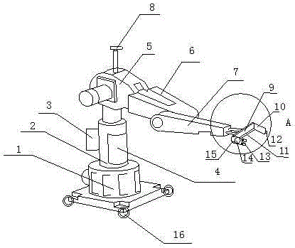
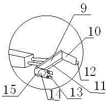
[0019] Such as figure 1 As shown, the present invention includes a base 1, and also includes a support member 2 installed on the base 1, a first arm 5, a second arm 6, a third arm 7, grabbing claws 9 and a suction cup 14, the first One arm 5, the second arm 6 and the third arm 7 are connected in series successively, and one end of the first arm 5 is also installed on the top of the support member 2, and the grab claw 9 is also connected on one end of the third arm 7; the support member The inside of 2 is also provided with interconnected controller 4 and acquisition card, motor 3 is also installed on the outer wall of support member 2, and camera 8 is also installed on the top of the first arm 5, motor 3, camera 8 and the third arm 7 all Connected on the controller 4; the grabbing claw 9 is provided with a sliding grabbing plate 10 and a chute 11, the sliding grabbing plate 10 can slide back and forth on the chute 11, and on the grabbing claw 9 and the sliding grabbing plate ...

Embodiment 2

[0022] This embodiment is preferably as follows on the basis of Embodiment 1: the sliding and grabbing plate 10 can rotate parallel to the chute 11 , and the buckle 12 can rotate and be parallel to the sliding grabbing plate 10 . When the grabbing operation of the parts can be realized by moving the sliding grabbing plate at ordinary times, the buckle can be rotated to fit the sliding grabbing plate, and the buckle slot can be rotated to fit the vertical plate to avoid buckling and buckling The groove blocks the gripping operation when the gripping jaws use the sliding gripping plate and the riser to facilitate gripping of parts.

[0023] The vertical plate and the horizontal plate on the grasping claw 9 are connected by a connecting piece 15 . If some parts are damaged, it is convenient to replace them separately later.

[0024] The camera 8 can rotate at any angle of 360°. The design of the camera can facilitate the camera to adjust the angle to take pictures of parts with...


PUM


Abstract

The invention discloses an automatic grabbing machine convenient to move. The automatic grabbing machine convenient to move comprises a base and further comprises a supporting part, a first arm, a second arm, a third arm, a grabbing claw and a suction cup, wherein the supporting part, the first arm, the second arm, the third arm, the grabbing claw and the suction cup are installed on the base. The first arm, the second arm and the third arm are connected in series in sequence. One end of the first arm is further installed at the top of the supporting part. A controller and a collecting card which are connected are further arranged in the supporting part. The grabbing claw is provided with a sliding grabbing plate and a sliding groove. The sliding grabbing plate can slide back and forth on the sliding groove. The suction cup is further arranged on the vertical plate and the side face of the sliding grabbing plate. A buckle groove is further formed in the end face of the vertical plate. A buckle matched with the buckle groove is formed in the end face of the sliding grabbing plate. Wheels are arranged at the four corners of the base. By means of the above structure, different sizes of parts, especially small parts, can be grabbed, and the automatic grabbing machine is easy and convenient to carry and capable of saving time and labor.

Description

technical field [0001] The invention relates to the processing field, in particular to a mobile and convenient automatic grabbing machine. Background technique [0002] Industrial robots can meet the needs of today's industrial cost and time efficiency, as well as the flexibility of material processing. With their advantages of high efficiency, low cost, and good flexibility, they can be used as automated processing equipment to replace traditional machining units. In recent years, compared with CNC machining centers, FMC and other processing equipment, industrial robots used in the field of mechanical processing have the advantages of low cost, high degree of automation, good flexibility, small installation space, etc., and can adapt to multi-variety, small batch, on-site processing It can meet the complex processing requirements such as free-form surfaces and complex cavities. Traditional industrial machine processing uses a fixed processing trajectory, which has poor ada...

Claims


Application Information

Patent Timeline
Patent Type & Authority Applications(China)
IPC IPC(8): B65G47/90B65G47/91
CPCB65G47/905B65G47/904B65G47/91
Inventor 张楠魏艾
Owner CHENGDU BEISEN WEIREN TECH CO LTD
Why Eureka
Try Eureka