Disc-type linear cutter winding device allowing locations of winding rollers to be adjustable

A winding device, disc-type technology, applied in the direction of winding strips, transportation and packaging, thin material processing, etc., can solve the problem that the winding work cannot be carried out smoothly, the winding roller cannot be aligned with the strip, and cannot be easily Good realization of winding and other issues, to achieve the effect of realizing winding operation, preventing displacement and jumping, and high reliability

Inactive Publication Date: 2016-07-20
CHONGQING SINSTAR PACKAGING MACHINERY
View PDF0 Cites 0 Cited by
  • Summary
  • Abstract
  • Description
  • Claims
  • Application Information

AI Technical Summary

Problems solved by technology

Although the existing cutter mechanism can meet the requirements of use to a certain extent, due to the long arc motion stroke of the cutter, there is a large impact force when it cuts the strip; in addition, after the strip is cut , can not fit well with the new winding roller, so that the winding work cannot be carried out smoothly
[0005] In addition, the existing winding mechanism is generally fixedly installed on the ground relative to the coil material processing production line. When the winding position of the strip material deviates laterally, the winding roller of the winding mechanism cannot be aligned with the strip material, which cannot be done well. rewinding
When winding, if the axis of the winding roller is not parallel to the surface of the strip, the speed of the strip will be inconsistent during winding, that is, there will be a problem that one end of the strip is loose and the other end is tight during winding, which is not true. Facilitate the winding operation of the strip

Method used


Image

  • Disc-type linear cutter winding device allowing locations of winding rollers to be adjustable
  • Disc-type linear cutter winding device allowing locations of winding rollers to be adjustable
  • Disc-type linear cutter winding device allowing locations of winding rollers to be adjustable

Examples


Embodiment Construction

[0033] The present invention will be further described below in conjunction with the accompanying drawings and specific embodiments, so that those skilled in the art can better understand the present invention and implement it, but the examples given are not intended to limit the present invention.

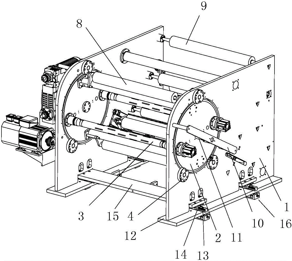
[0034] like figure 1As shown, it is a structural schematic diagram of an embodiment of a disc-type linear cutter winding device with an adjustable winding roller position in the present invention. The disc-type linear cutter rewinding device with adjustable rewinding roller position in this embodiment includes two brackets 1 located at both ends. The two brackets 1 are correspondingly provided with coaxial mounting holes, and the mounting holes are provided with a Disc-type roller stands 2 with gap fit, and two winding rollers 3 that are rotatably matched with the two disc-type roller stands 2 are arranged between them. The support 1 is provided with a rotating support unit for r...


PUM


Abstract

The invention discloses a disc-type linear cutter winding device allowing locations of winding rollers to be adjustable. The disc-type linear cutter winding device comprises two supports located at the two ends. Coaxial mounting holes are formed in the two supports correspondingly. Disc-type roller stands in clearance fit with the mounting holes are arranged in the mounting holes. The winding rollers are arranged between the two disc-type roller stands. The supports are provided with rotary supporting units. Each rotary supporting unit comprises two baffles, wherein a rotary shaft is arranged between the two baffles and sleeved with a bearing I, and the two baffles are provided with bearings II. Mounting bases are arranged below the two supports and provided with at least two sliding rails, and sliding grooves matched with the sliding rails are formed in the bottoms of the supports. The bottom face of each mounting base is provided with a regulating base. Each regulating base comprises a bottom board and a regulating bevel board, wherein the matching faces between the bottom board and the regulating bevel board are tilting slopes, and a drive mechanism is arranged between the bottom board and the regulating bevel board. The disc-type linear cutter winding device further comprises linear cutter mechanisms. Each linear cutter mechanism comprises a kiss-roller and cutters, and the two ends of each kiss-roller are provided with linear drive mechanisms.

Description

technical field [0001] The invention belongs to the technical field of strip winding mechanisms, and in particular relates to a disc type linear cutter winding device with an adjustable winding roller position. Background technique [0002] The winding mechanism is the unwinding or rewinding part of the coil material processing production line. When unwinding, it is mainly used to unwind the rolled raw materials mechanically. The winding mechanism is widely used in the paper roll, cloth roll, plastic roll and metal coil processing production line, and the design is diversified according to the actual process requirements. [0003] The existing winding mechanism generally includes brackets located at both ends, a roll frame is arranged between the two brackets, at least one winding roller is arranged between the two roll frames, and the two roll frames are respectively rotatably fitted on two on the stand. The unwinding of the strip can be realized by driving the winding ro...

Claims


Application Information

Patent Timeline
IPC IPC(8): B65H19/26B65H19/30B65H23/032B65H18/02B65H19/28
Inventor 罗朝建李永才陈跃华
Owner CHONGQING SINSTAR PACKAGING MACHINERY
Why Eureka
Try Eureka