Double beam floor structure

A technology for cover structure and floor covering, which is applied to floor slabs, building components, building structures, etc., can solve the problems of inability to standardize the production of main components in factories, poor ductility of beamless slabs, etc., and achieve easy processing and installation, reduce beam height, cost saving effect

Active Publication Date: 2016-07-20
杨大刚
View PDF8 Cites 8 Cited by
  • Summary
  • Abstract
  • Description
  • Claims
  • Application Information

AI Technical Summary

Problems solved by technology

[0004] Because there are no beams in the beamless floor structure, the load on the slab surface is directly transmitted from the slab to the column. It has the advantages of simple structure, simple force transmission path, high clearance utilization rate, and beautiful appearance. It is conducive to ventilation, easy to arrange pipelines and construction. However, the beamless floor structure requires thicker slabs and higher strength concrete and steel bars. From the perspective of structural performance, the ductility of the beamless slab is poor, and the failure of the slab at the column cap or column top is a brittle shock. cut damage
[0005] The beamless hollow floor structure is an improved version of the beamless floor structure. Although it overcomes some shortcomings of the beamless floor structure, it still needs to process steel bars at the construction site, bind the steel bars, and then pour concrete on site to complete the beam and floor. Formwork and full scaffolding are required for pouring concrete, and the main components cannot be manufactured in a standardized manner in a factory

Method used


Image

  • Double beam floor structure
  • Double beam floor structure
  • Double beam floor structure

Examples


Embodiment 1

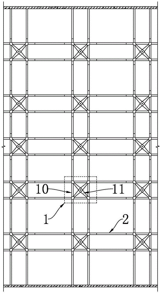
[0037] Such as figure 1 , 2 As shown in, 3, 4, and 10, the present invention provides a double-beam floor structure, which includes several supporting units 1 that play a supporting role. The number and density of the supporting units 1 are determined according to the actual needs of the floor. , Adjacent support units 1 are connected by two parallel vertical and horizontal beams 2, and then a square-hole mesh structure with the supporting unit 1 as the node and the vertical and horizontal beams 2 as the link is formed; this kind of square-hole mesh support The structure is easy to process and install, with fewer types of components and strong standardization, which improves installation efficiency.

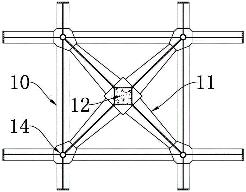
[0038] More specifically, such as figure 1 , 2 , 3, and 4, the support unit 1 of this embodiment includes a cross beam 10, a cross beam 11, and a support column 12. In the present invention, the supporting beams are all on the side of the support column 12, and the cross beam 11 is p...

Embodiment 2

[0041] The double-beam floor structure of the second embodiment is basically the same as that of the first embodiment, and the difference lies in that the structure of the tic-shaped beam 10 and the connection mode between the supporting units 1 of the present embodiment are different from those of the first embodiment.

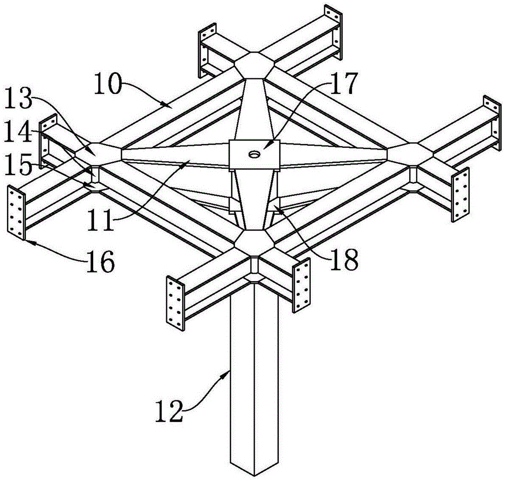
[0042] Specifically, such as Figure 5 , 6 As shown in, 7, 8, 9, 10, the well-shaped beam 10 includes H-shaped steel A20, H-shaped steel B21 and H-shaped steel C22. Two H-shaped steels B21 and two H-shaped steels B21 are welded between two H-shaped steels A20 arranged in parallel. The distance between the two H-shaped steels A20 is the same. The H-shaped steel B21 is perpendicular to the H-shaped steel A20; the H-shaped steel C22 is welded to the outside of the H-shaped steel A20 and is in a straight line with the H-shaped steel B21. The above-mentioned H-shaped steel A20 , H-shaped steel B21 and H-shaped steel C22 form the Tic-Tac-beam 10 structure; the end of t...


PUM


Abstract

The invention discloses a double beam floor structure. The double beam floor structure comprises supporting units. Every two adjacent supporting units are connected through two parallel longitudinal beams or two parallel cross beams to form a square-hole netty structure with the supporting units as nodes and the longitudinal beams and the cross beams as links. Each supporting unit comprises a groined beam, a rood beam and a supporting column, wherein the rood beam is arranged in the center of the groined beam and is connected with the cross points of the groined beam, and the supporting column is fixedly connected with the center of the rood beam. According to the double beam floor structure, the square-hole netty structure is formed through the supporting units, the longitudinal beams and the cross beams. Compared with traditional beam-slab type floor structures, primary beams and secondary beams are not distinguished in the netty structure any more, and force transfer between the beams, between the beams and floorslabs, as well as between the beams and the supporting columns is more uniform, the condition that part of the beams are not stressed uniformly and accordingly waste is caused is avoided, and the double beam floor structure has the advantages that the load-bearing effect is good, the height of the beams is decreased, and the cost is reduced.

Description

Technical field [0001] The invention relates to the field of building structures, and more specifically, to a supporting structure system of a floor cover, which is a double-beam floor structure. Background technique [0002] The current structural systems used in the construction of floor coverings mainly include ordinary beam-slab structures, beamless floor structures and hollow beamless floor structures. [0003] The ordinary beam-slab structure requires the main beam and more secondary beams arranged on the main beam, so the beam height of the ordinary beam-slab structure is relatively large, and the required floor height is very high. [0004] Because the beamless floor structure does not have beams, the load on the slab surface is directly transmitted from the slab to the column. It has the advantages of simple structure, simple force transmission path, high headroom utilization, and beautiful appearance. It is good for ventilation, easy to arrange pipelines and construction. ...

Claims


Application Information

Patent Timeline
Patent Type & Authority Applications(China)
IPC IPC(8): E04B5/14
CPCE04B5/14
Inventor 杨大刚
Owner 杨大刚
Why Eureka
Try Eureka