Peak regulation energy storage system for condensed steam type turbine unit and operation adjusting method

A steam turbine unit, condensing steam technology, applied in the direction of steam engine devices, mechanical equipment, machines/engines, etc., can solve the problems of inconsistent heat supply demand, large steam extraction, and deep peak-shaving function of the unit without consideration, etc. To achieve the effect of alleviating the thermal and electrical contradictions

Inactive Publication Date: 2016-07-20
HUADIAN ELECTRIC POWER SCI INST CO LTD
View PDF4 Cites 12 Cited by
  • Summary
  • Abstract
  • Description
  • Claims
  • Application Information

AI Technical Summary

Problems solved by technology

[0004] The simple optical axis rotor operation mode, due to its large steam extraction, is constrained by the small heating load in the early and late stages of heating, so that the unit in the optical axis rotor operation mode cannot be put into operation in the early and late stages of heating.
At present, no heating unit in China is equipped with

Method used


Image

  • Peak regulation energy storage system for condensed steam type turbine unit and operation adjusting method
  • Peak regulation energy storage system for condensed steam type turbine unit and operation adjusting method

Examples


Embodiment 1

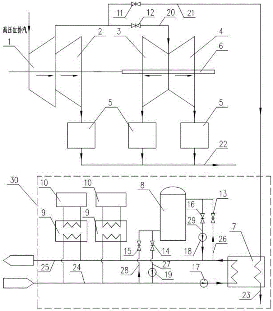
[0042] like figure 1 As shown, the peak shaving energy storage system of the condensing steam turbine unit in this embodiment is composed of a steam turbine low-pressure cylinder optical axis rotor unit and a heat storage and discharge device 30 .

[0043] The steam turbine low-pressure cylinder optical axis rotor unit includes medium-pressure cylinder 1, first low-pressure cylinder 2, low-pressure cylinder steam guide pipe 20, low-pressure cylinder steam guide pipe extraction branch pipe 21, second low-pressure cylinder 3, third low-pressure cylinder 4, condensing steam Device 5, condensation water pipe 22 and optical axis rotor 6. The medium pressure cylinder 1, the first low pressure cylinder 2, the second low pressure cylinder 3, the third low pressure cylinder 4 and the optical axis rotor 6 are coaxially connected; the exhaust port of the medium pressure cylinder 1 is connected with the steam guide pipe 20 of the low pressure cylinder; the second low pressure cylinder 3 ...

Embodiment 2

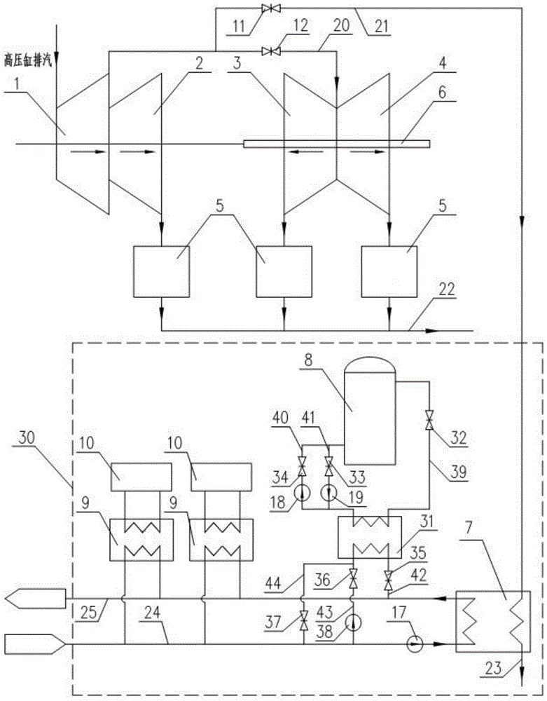
[0067] like figure 2 As shown, this embodiment is composed of a steam turbine low-pressure cylinder optical axis rotor unit and a heat storage and release device 30 .

[0068] The steam turbine low-pressure cylinder optical axis rotor unit includes medium-pressure cylinder 1, first low-pressure cylinder 2, low-pressure cylinder steam guide pipe 20, low-pressure cylinder steam guide pipe extraction branch pipe 21, second low-pressure cylinder 3, third low-pressure cylinder 4, condensing steam Device 5, condensation water pipe 22 and optical axis rotor 6. The medium-pressure cylinder 1, the first low-pressure cylinder 2, the second low-pressure cylinder 3, the third low-pressure cylinder 4 and the optical axis rotor 6 are coaxially connected; the exhaust port of the medium-pressure cylinder 1 is connected to the steam guide pipe 20 of the low-pressure cylinder; The steam inlets of the cylinder 3 and the third low-pressure cylinder 4 are connected with the steam guide pipe 20 o...


PUM


Abstract

The invention relates to a peak regulation energy storage system for a condensed steam type turbine unit and an operation adjusting method of the peak regulation energy storage system. By means of the optical axis rotor technology, steam is extracted to be used for supplying heat, so that electrical loads of the unit are reduced; and then a heat storing and releasing system is arranged, the functions of peak clipping and valley filling of the system are utilized, and on the premise of meeting heat loads in the heating season, the electrical loads of the unit are reduced to the minimum. The electricity and heat contradiction within the heating period in the northern area can be relieved, flexibility and elasticity of power grid dispatching are improved, and the system is suitable for being vigorously popularized.

Description

technical field [0001] The invention relates to the technical field of heat supply, in particular to a peak regulation energy storage system and an operation regulation method of a condensing steam turbine unit. Background technique [0002] At present, the domestic demand for electricity is growing slowly, and the contradiction of excess electricity is becoming more and more prominent. On the other hand, the heating market is growing day by day, and more and more pure condensing units are being transformed into heating units. With the rapid development of clean energy wind power technology, hydropower technology, and photovoltaic technology, clean energy power generation technology should be given priority in the power dispatching process. However, in some areas, due to the inability of the power grid to fully consume, the problems of abandoning wind, water and light are becoming more and more serious, which has become the main contradiction affecting the healthy developmen...

Claims


Application Information

Patent Timeline
IPC IPC(8): F01K13/02F01K11/02
CPCF01K13/02F01K11/02
Inventor 陈菁孙士恩高新勇庞建锋何晓红洪纯珩马光耀
Owner HUADIAN ELECTRIC POWER SCI INST CO LTD
Why Eureka
Try Eureka